
I Automated Pressure Advance Using a Bed-Leveling Sensor
Automatic Pressure Advance calibration with a Prusa nozzle load cell: how a bed-leveling sensor can tune K values, find max flow, and monitor prints.
TL;DRthe short version
- Pressure Advance depends on the filament, not just the printer, so it should ideally be calibrated for every spool, yet almost everyone still prints a test pattern and picks a line by eye.
- Bambu Lab automated this years ago, but hardly anyone else did, even though newer Prusa printers already carry the necessary hardware: the Nextruder load cell, which so far only touches the build plate.
- Extruding into free air with a slow-fast-slow pattern makes the pressure lag directly visible in the nozzle force: too low K gives a slow, rounded response, the right K follows the commanded square wave, too high K over- and undershoots.
- I built a free, open-source web tool that generates the G-code, records Prusa's live metrics stream and sweeps through K values automatically.
- The most reliable metric turned out not to be the deviation from the ideal square wave, where synchronizing the timing is the weak point, but the undershoot on the fast-to-slow transition. The tool picks the last K value before it appears.
- Compared against printed pattern tests, the automatic result landed exactly on or slightly above my manual pick for most materials. Only hot-printed ASA was clearly off.
- The same sensor could also determine the real maximum volumetric flow, probe for axis skew, and enable actual process monitoring: clogs, crashes, unstable extrusion.
- Why isn't this everywhere? Bambu Lab holds patents on the camera-based approach in China, the US and Europe. The force-based method appears to be patented only in China, which leaves room for others to follow.
Why Pressure Advance needs calibration
Pressure Advance is one of the most important settings on a modern high-speed 3D printer. It is what prevents these ugly, over-extruded corners and the corresponding under-extrusion after a sudden acceleration. The reason we need it is that the extrusion system behaves a little like a spring. Even though filament feels quite stiff, it still compresses when the extruder pushes it into the hotend. After all, a significant force is required to squeeze molten plastic through the tiny nozzle opening. When the printer suddenly slows down, the extruder gears may stop moving, but the filament is still compressed. The stored pressure continues pushing material out of the nozzle, creating an over-extruded corner. When the printer accelerates again, the opposite happens. Some of the extruder movement initially goes into compressing the filament and rebuilding pressure, so the material flow briefly falls behind.
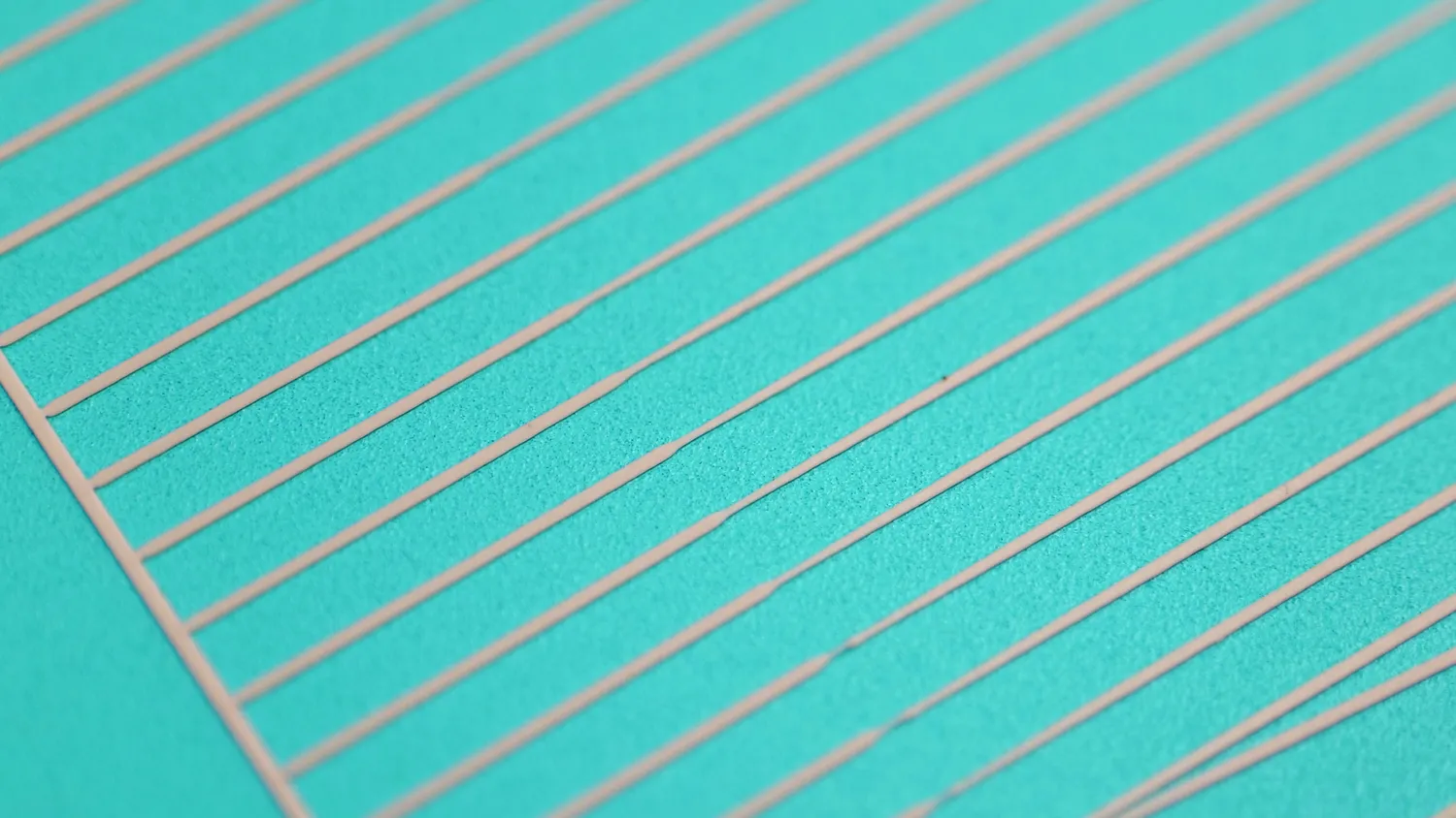
Line width changes after speed transitions
On older, slower printers, this was less noticeable because speed changes happened more gradually and the extrusion rates were lower. But on modern machines, the printer constantly accelerates, decelerates, and changes direction at very high speeds.
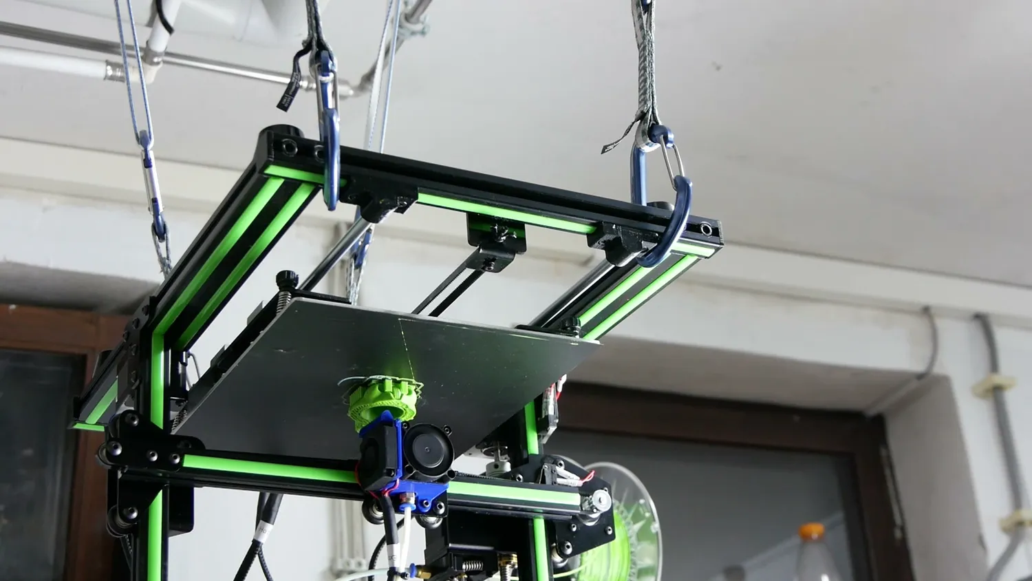
An older, slower 3D printer
Pressure Advance compensates for this delayed response.
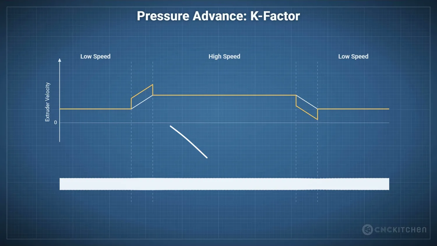
Pressure Advance modifies extruder velocity
During acceleration, the firmware briefly commands additional extruder movement to build pressure more quickly. During deceleration, it reduces the extrusion amount and may even briefly pull the filament back to release pressure before the motion stops.
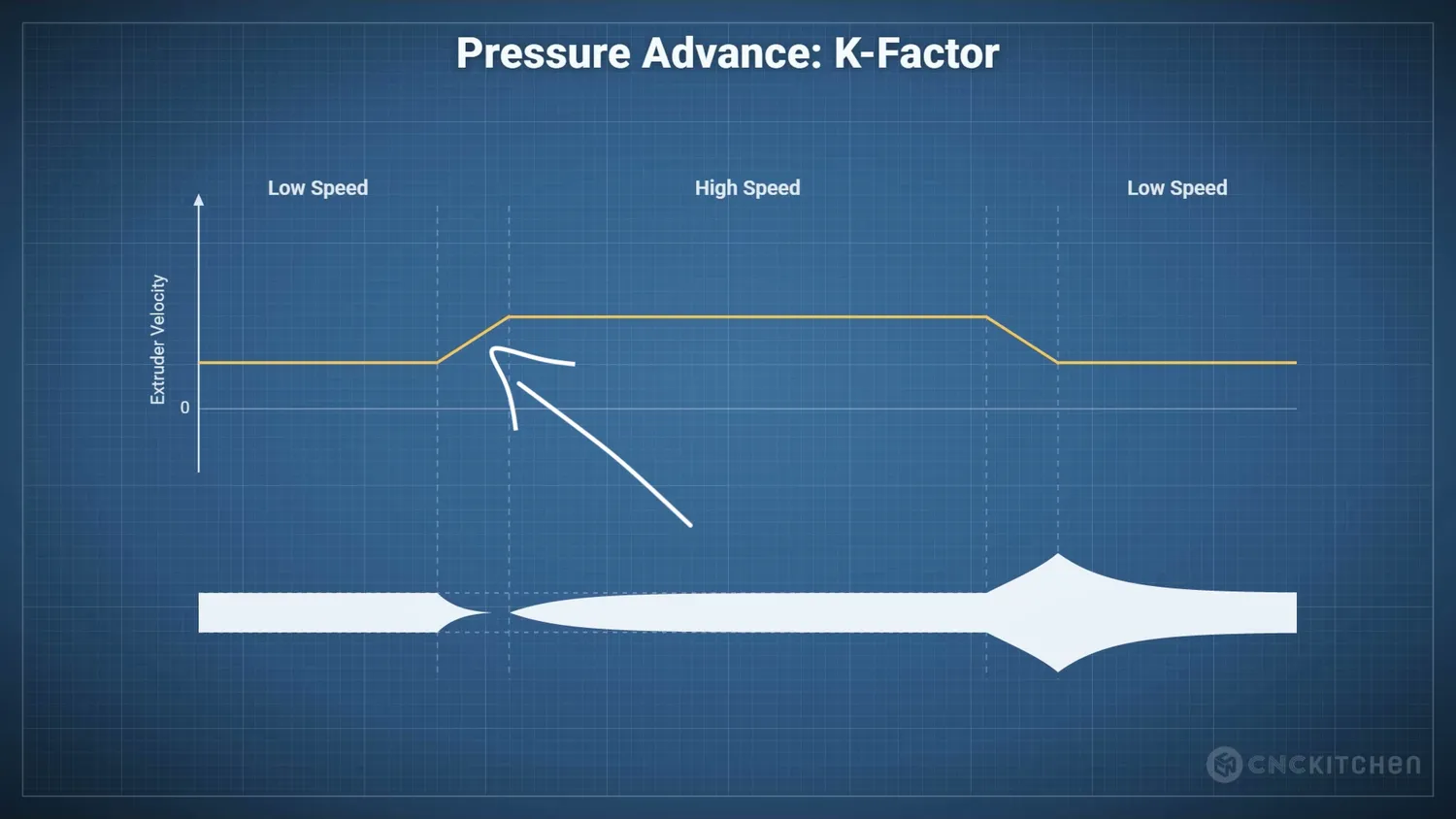
Extra extruder movement during acceleration
With the correct value, the actual material flow follows the commanded extrusion much more closely.
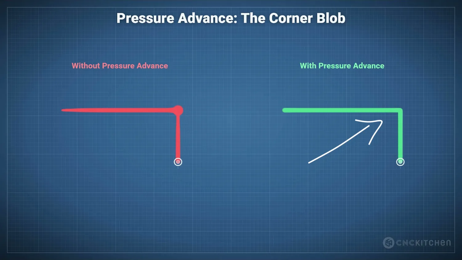
Corner quality without and with Pressure Advance
But the amount of compensation needs to be tuned. If the Pressure Advance value is too low, the corners remain over-extruded. If it is too high, the corners become under-extruded instead and your parts show holes!
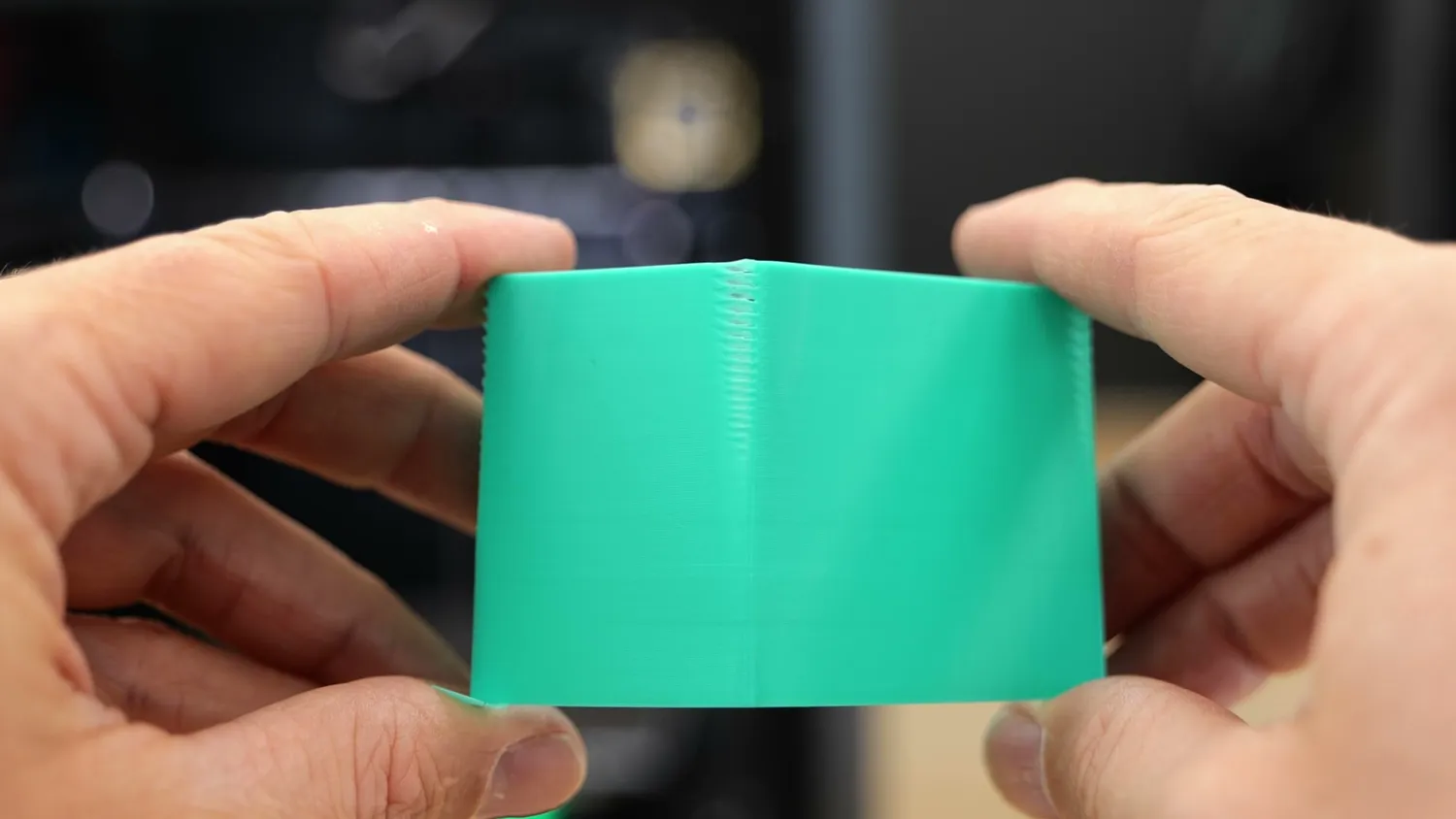
Corner artifacts from a wrong K value
This compensation factor is usually called the Pressure Advance, PA, or K value.
Traditionally, we calibrate it by printing a test pattern. One of the simplest versions consists of several lines that transition from slow to fast and back to slow again. Every line uses a different K value.
Once the test is finished, you inspect the lines, select the one with the most consistent width, and enter that value into your slicer or printer configuration.
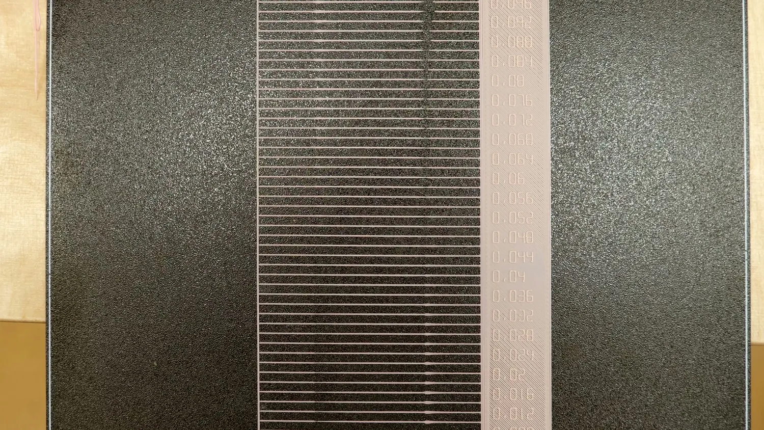
Classic Pressure Advance line calibration pattern
There are now more practical tests that use corners or a small tower, but they all follow the same basic principle: print at several different Pressure Advance values and visually select the one that looks best.
The problem is that Pressure Advance is not simply a setting for the printer. It depends heavily on the filament.
Different polymers have different stiffnesses and melt-flow behavior. Even two colors of the same filament can behave differently because their pigments and additives change the material properties.
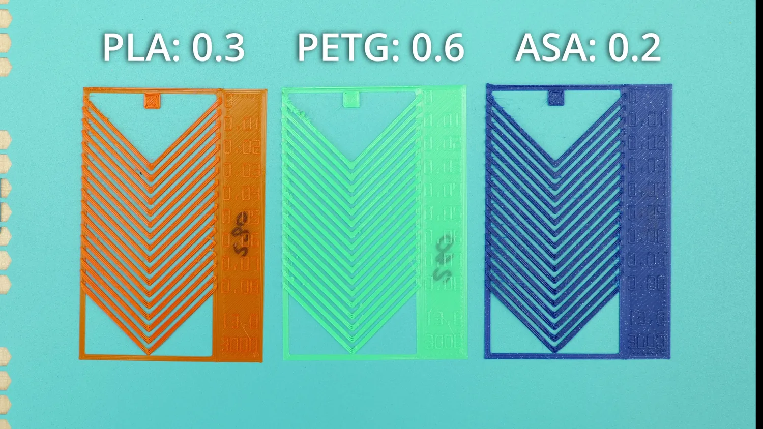
PLA, PETG and ASA need different K values
You can often get away with using a rough value for each material type. But especially on fast prints, a value that is too far off can become clearly visible. So ideally you should calibrate that value before every print!
Bambu Lab’s automatic calibration
This is why Bambu Lab* automated the process. The original X1 printed a small pattern containing different extrusion conditions, scanned it using its LiDAR system, and automatically calculated the optimal K value. In principle, this is very similar to our manual test, except that the pattern is more compact and the evaluation is automated.
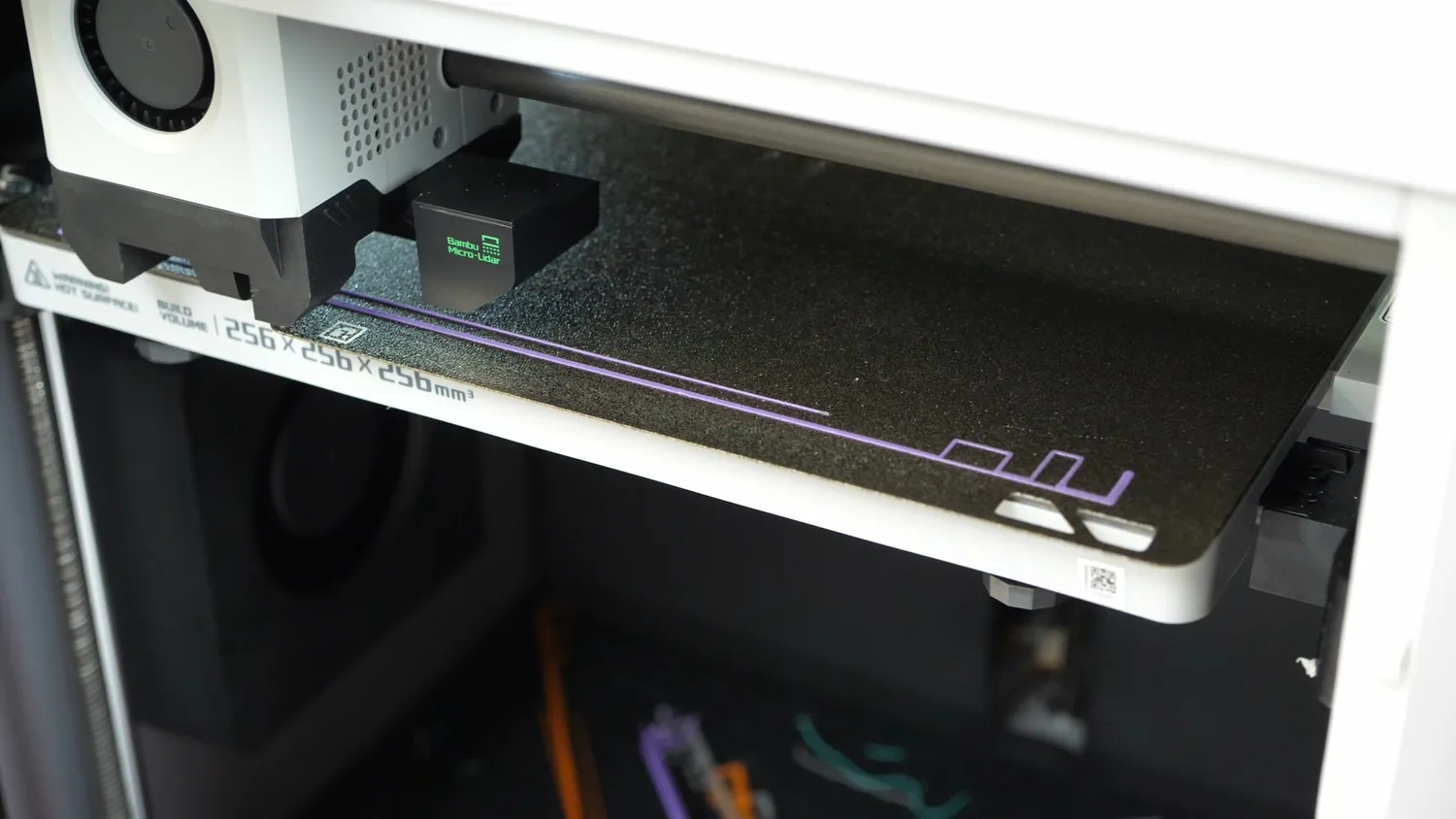
Bambu Lab X1 LiDAR flow calibration
Newer Bambu Lab machines no longer need to print the calibration pattern onto the build plate. Instead, they perform an extrusion routine in the purge area and analyze the response using a sensor in the hotend.
But despite the obvious benefits, almost no other manufacturers also offer automatic Pressure Advance calibration.
And this is strange, because I’m confident that several printers already include much of the hardware that should be required.
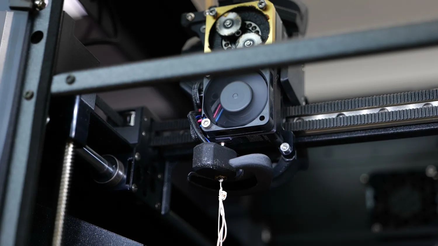
All newer Prusa* printers equipped with the Nextruder, for example, contain a load cell in the printhead. Its main purpose is nozzle-based bed probing, but it can also measure the force acting on the nozzle during extrusion.
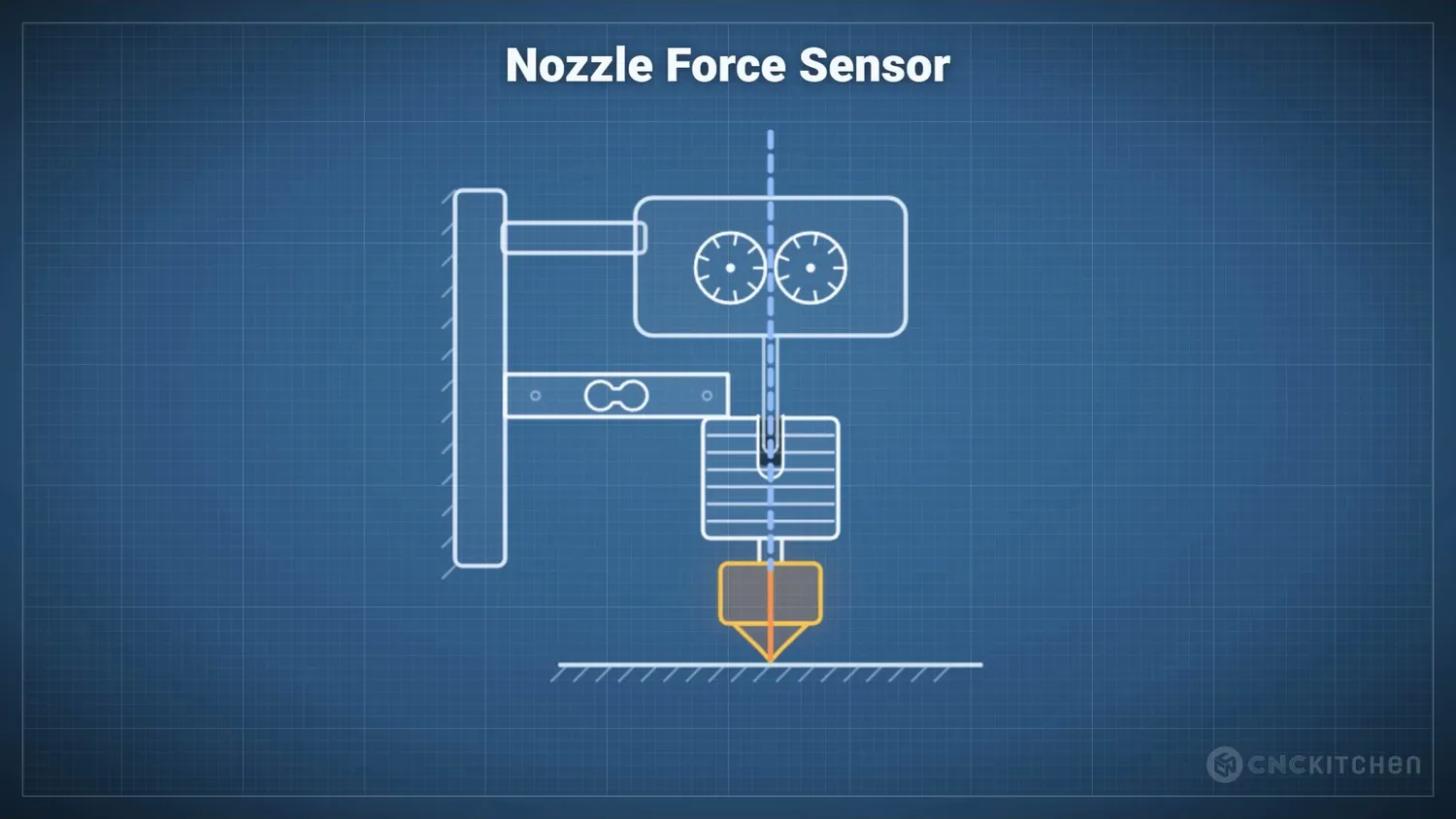
The Nextruder load cell measures nozzle forces
So my question was simple: Can we use that force signal to automatically determine Pressure Advance?
Instead of printing a calibration object, could the printer simply extrude some filament into free air, measure the response, and calculate the K value directly?
That is what I wanted to find out.
A look at the Snapmaker U1
The first printer I looked at was actually not the Prusa, but the Snapmaker U1*.
The U1 is basically what you might get if a Prusa XL* and a Bambu Lab X1 had a baby. It also performs automatic Pressure Advance calibration by purging filament using a repeated slow-fast-slow extrusion pattern.
During this routine, the printer varies the K value and monitors the response using a sensor inside the toolhead.
The interesting part is that the U1 runs Klipper-based firmware and much of its code is publicly available. So in principle, this could provide some insight into how automatic calibration works.
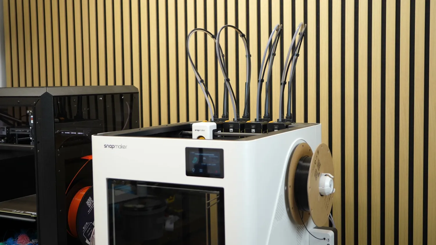
The Snapmaker U1 runs Klipper-based firmware
The test commands themselves are visible. We can see the slow-fast-slow extrusion pattern, the tested K values, and the sensor data being collected.
But part of the final evaluation appears to happen in a separate process that is not part of Klipper and therefore I also don’t have any code for it.
So we can observe what the printer does, but we cannot see exactly how it converts the sensor signal into the data that it uses to determine the K value.
So let’s look at the data ourselves and let’s try to figure it out.
Reading the Prusa nozzle load cell
Unfortunately, the U1 also does not provide convenient access to its live sensor data. But as said before newer Prusa printers have a very similar load-cell arrangement, and Prusa provides an open metrics interface that lets us monitor the nozzle-force signal remotely.
You enable metrics in the printer’s network menu, choose which data you want to transmit, and send it to a monitoring application on your computer.
After a little configuration, you can access a surprising amount of live information from the machine, including the nozzle load cell.
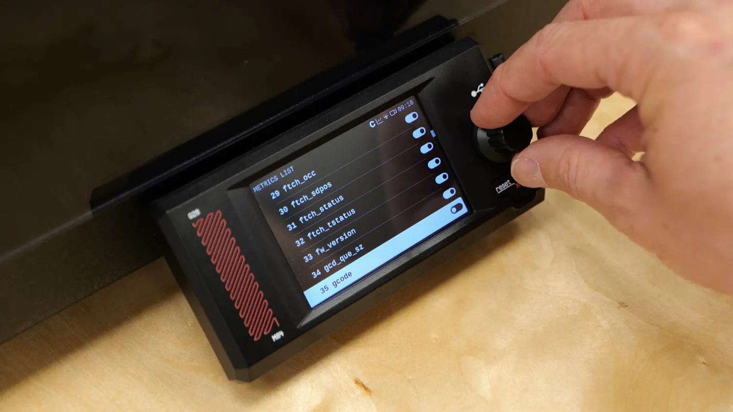
Metrics selection on the printer display
I’m not trying to shill for Prusa here, but for this kind of research, that is useful.
So I built a small web interface that connects to the printer and records the load-cell data.
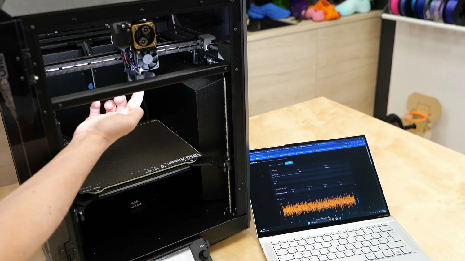
Recording live load-cell data
When I tap the nozzle, the force spike immediately appears in the graph.
And when I extrude filament, the sensor shows how much force is acting on the hotend assembly while the material is being pushed through it.
For the calibration test, the printer repeatedly switches between a low and a high extrusion rate. The commanded extrusion speed, therefore, looks like a square wave. I have a ton of measured data, but it’s easier to explain the effects with a schematic animation.
Now let’s look at the measured force response without any Pressure Advance.
At the low extrusion rate, the force settles at a relatively constant level.
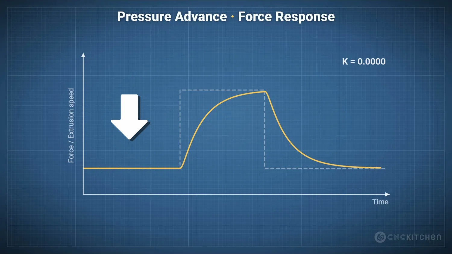
Force settles at the low extrusion rate
When the printer suddenly switches to the higher rate, the force starts increasing, but it does not rise instantly. It gradually approaches the new steady-state value.
When the extrusion rate drops again, the force also takes time to fall back down.
This delay is a representation of the same behavior that causes under- and over-extrusion during a print.
The commanded extrusion rate has already changed, but the mechanical pressure inside the extrusion system is still catching up.
Now we gradually increase the Pressure Advance value.
Pressure Advance adds a short burst of extruder movement during the acceleration and removes extrusion during the deceleration. As the K value increases, the measured force response begins to follow the commanded square wave more closely.
The rising and falling edges become steeper, and the delay becomes smaller.
At some point, the compensation is almost perfect. The force quickly reaches the new steady-state value without a large delay or overshoot.
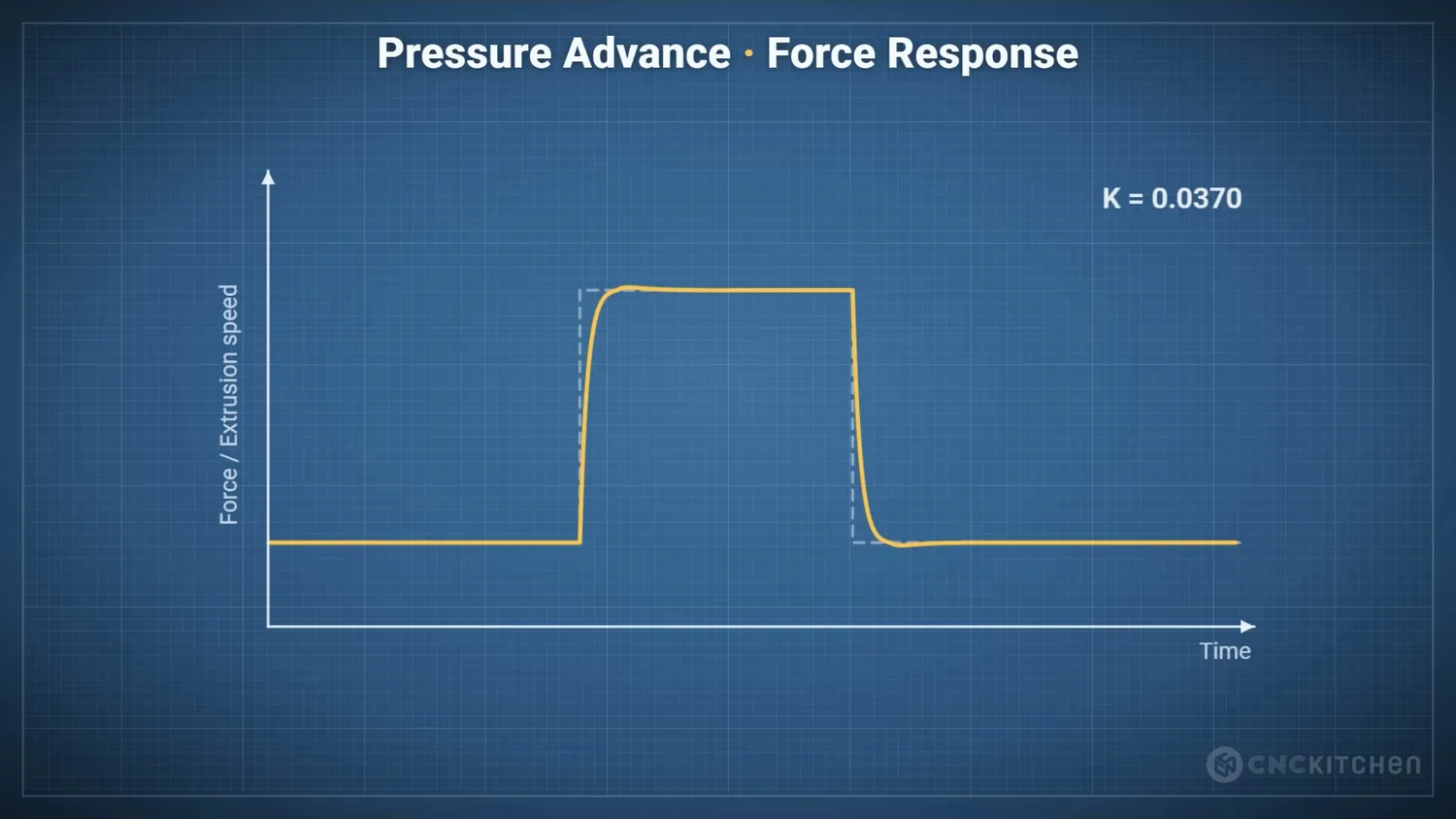
Almost perfect compensation
But if we increase K even further, the compensation becomes too aggressive.
During the transition to the higher flow rate, the force briefly rises above the steady-state level. And during the transition back to the slower rate, it drops below it.
So we get three characteristic responses.
With K too low, the force response is slow and rounded.
With a good K value, it closely follows the commanded change.
And with K too high, the response overshoots and undershoots.
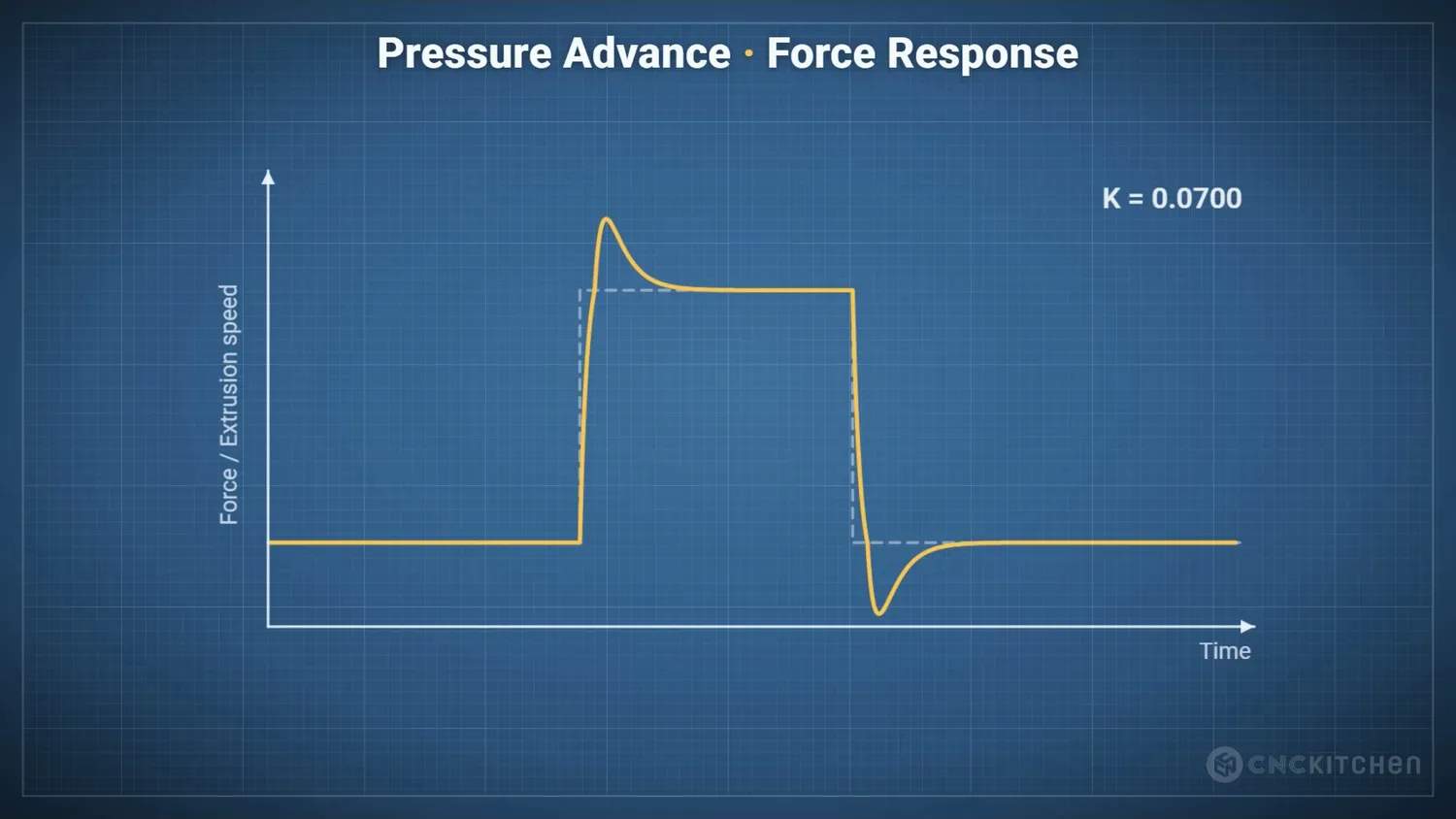
K too high: overshoot and undershoot
My assumption is that automatic calibration systems analyze these differences and select the K value that produces the best response.
My automatic Pressure Advance tuner
To test this idea, I created a web-based tool that automatically prepares and runs the calibration.
You select the desired nozzle temperature and start the test. The tool generates the G-code, sends it to the printer, and begins recording the load-cell data.
The printer heats up, moves to a safe position, and extrudes filament into free air using the slow-fast-slow pattern while gradually increasing the K value.
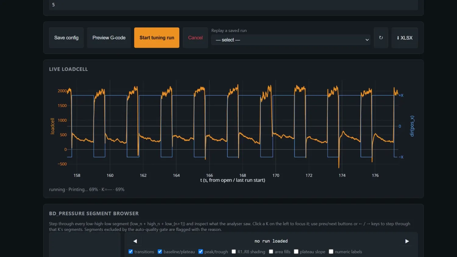
Once the sweep is complete, the tool separates the individual test sections and calculates several metrics for every K value.
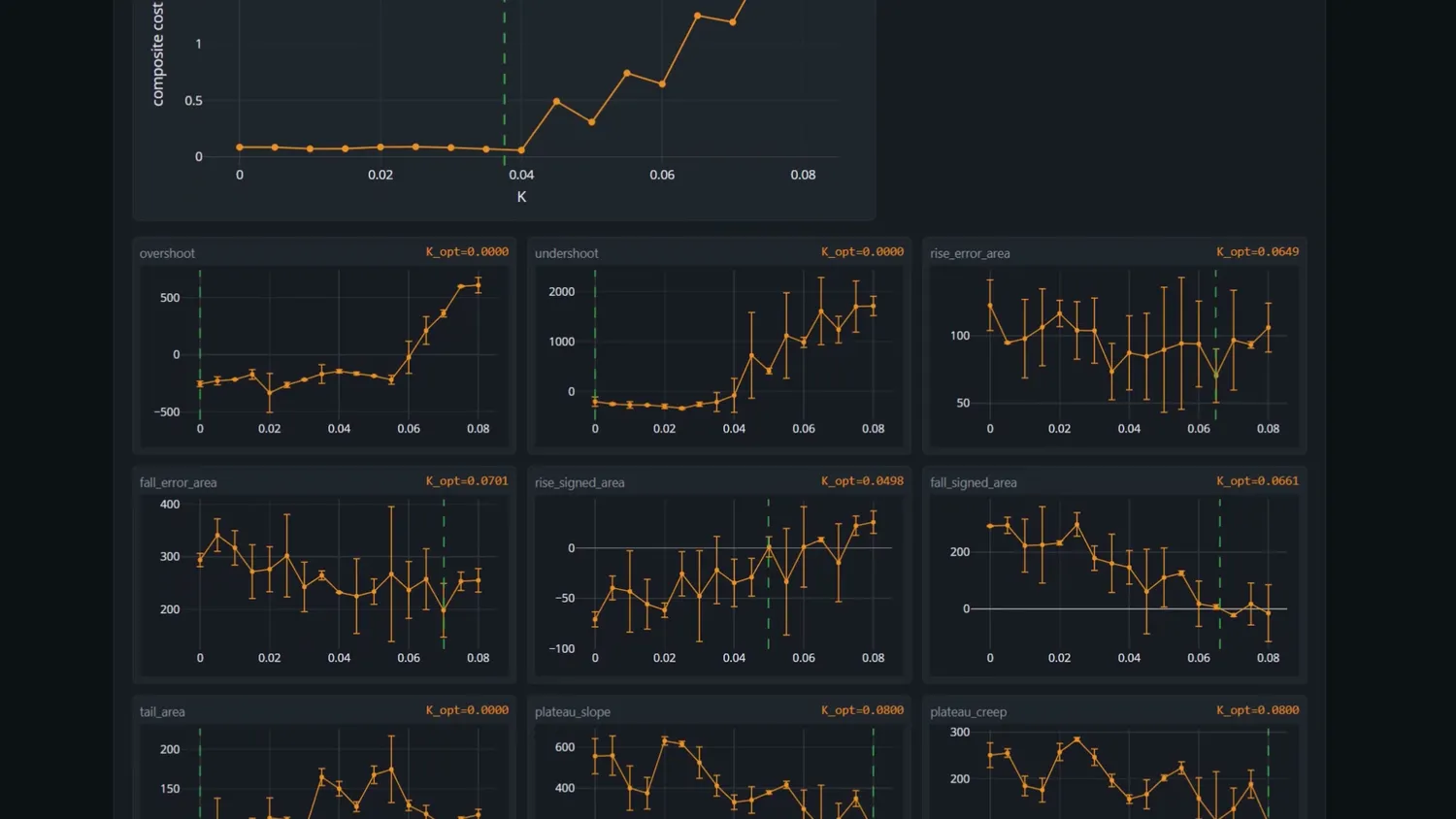
Calculated metrics for every K value
These include the overshoot after accelerating, the undershoot after decelerating, the slopes of the rising and falling edges, the settling behavior, and the total area between the measured force response and an idealized square wave.
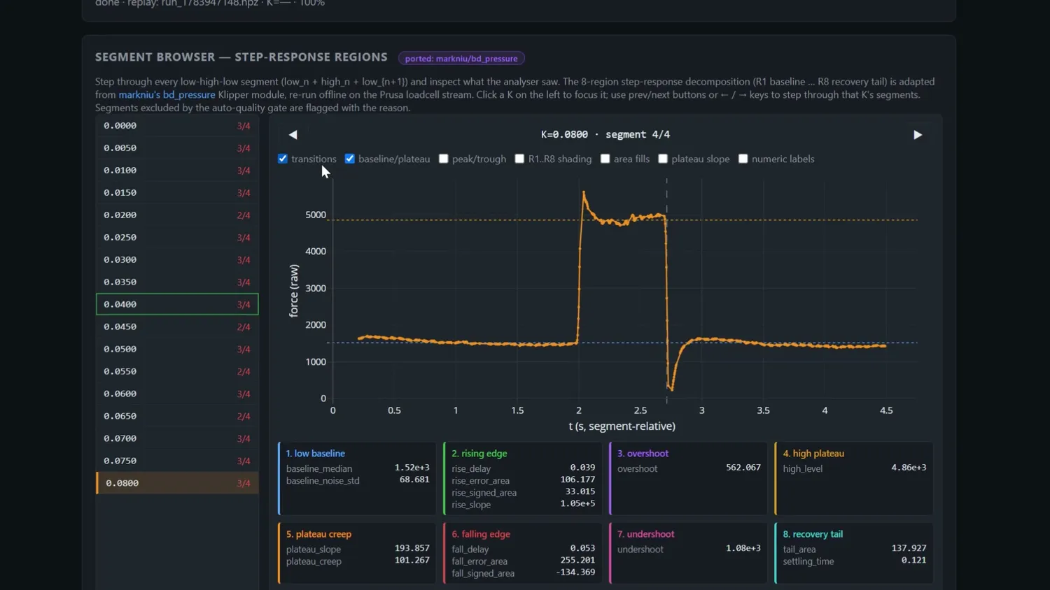
Step-response metrics for a single segment
At first, I expected the total error area, so how far we deviate from the ideal curve, to be the best metric because this is what the U1 probably uses.
But in practice, this did not give me the most reliable results.
One major problem, besides regularly some missing data, could be timing.
The Prusa metrics interface gives me the load-cell signal, but it does not provide the extruder position, which means I don’t know when exactly we start and stop extruding. So my tool needs to estimate when each extrusion transition begins and ends using the available data.
Even a small timing offset can significantly change the calculated deviation area.
This would be much easier if the analysis ran directly inside the printer firmware, because the firmware knows exactly when each extrusion command is executed.
Surprisingly, the most useful metric in my tests was much simpler: the undershoot after switching from fast extrusion back to slow extrusion.
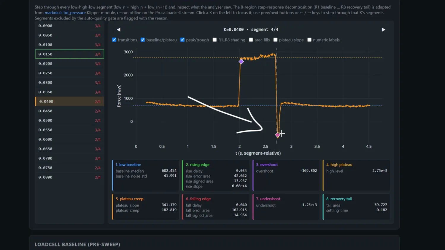
The undershoot after switching back to slow
With low K values, the force decreases toward the new steady-state value but does not fall below it.
As K increases, the response becomes faster.
But once the compensation becomes too aggressive, the measured force briefly drops below the steady-state level. That undershoot is a clear indication that the K value is now too high.
So instead of trying to find the mathematically perfect square wave, I can look for the point where compensation first becomes excessive.
The selected value is the final K value before a clear undershoot appears.
That is a much more robust signal in my current setup.
Does it match a printed calibration?
But a calibration graph can look convincing and still produce the wrong result. The important question is whether the automatically selected value agrees with a traditional printed calibration.
So I tested several different materials.
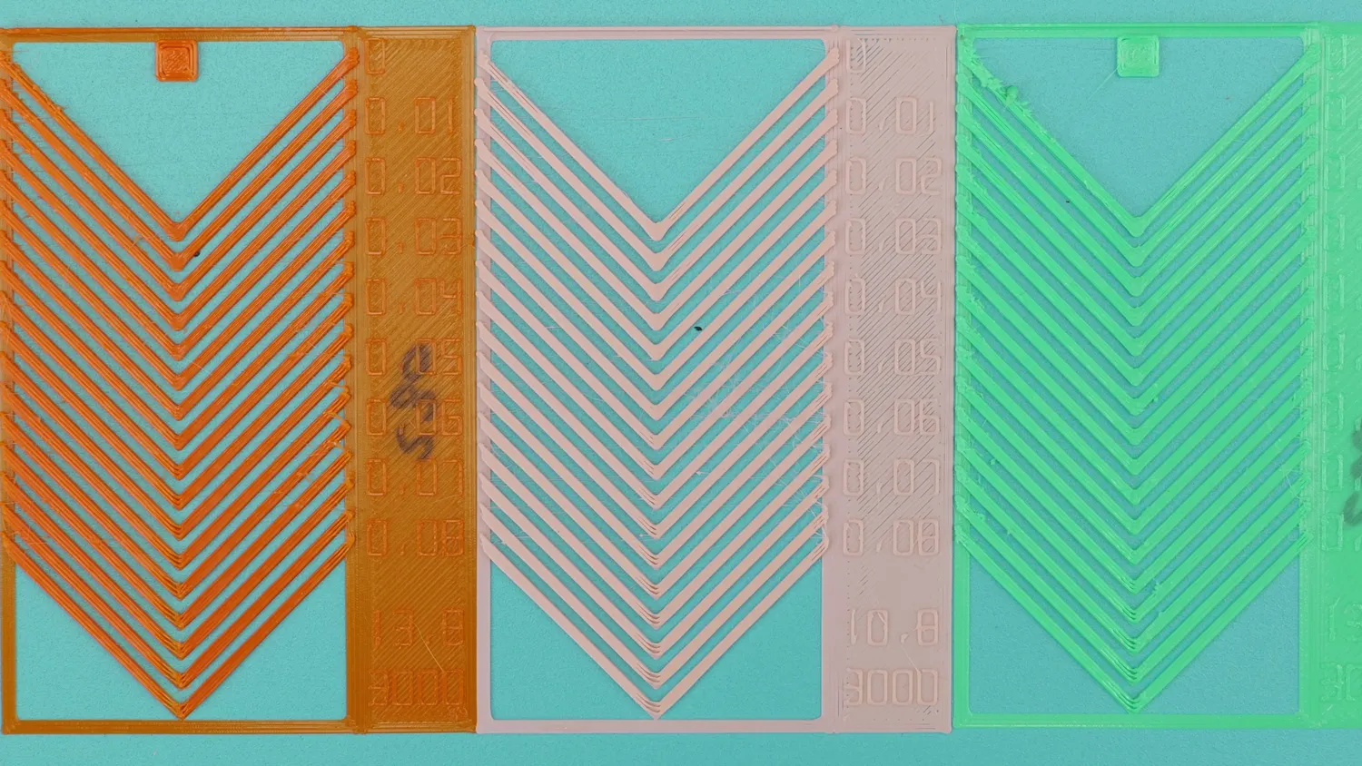
Printed Pressure Advance tests for each material
For each one, I first printed a conventional Pressure Advance test and manually selected the value that looked best. I then ran the automatic force-based calibration and compared the result.
And the results were surprisingly close. The Pattern Test is here our Ground Truth or what I would have selected if I had printed a manual test.
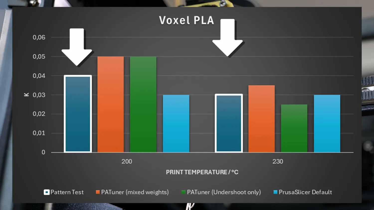
PA Tuner results vs. pattern test
Depending on the material, the automatically selected value was either exactly where I would have placed it manually or slightly higher. Only the hot printed ASA was more off.
That does not mean the method is finished or universally reliable. My sample size was still limited, and there definitely needs to be more work tuning the weights and the method. And who even says that a perfect square-wave force response produces the best print results? Interestingly, the U1 also has fallback values if the test looks odd. I have even heard people put tape over their Lidar Scanner on the X1 and still get good print results. So good defaults are definitely a reasonable starting point, but with the data we get, we can further refine them to improve the overall results!
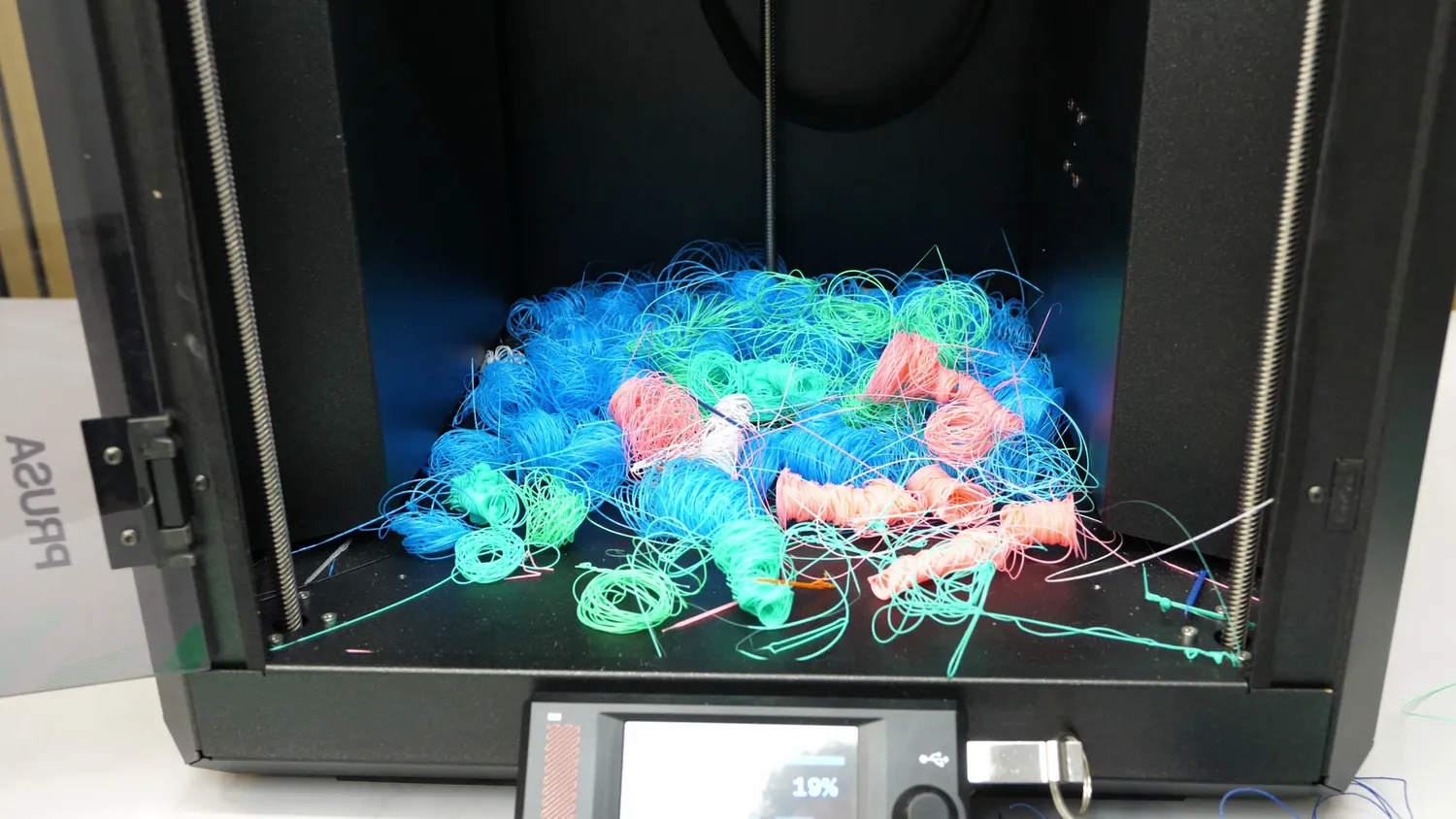
The leftovers of many calibration runs
And we can do it without printing a calibration object.
The test only needs to extrude a relatively small amount of filament into free air, and the evaluation can happen automatically.
My web tool is not yet a replacement for a properly integrated firmware implementation. The biggest limitations come from retrieving and synchronizing the sensor data externally.
But as a proof of concept, it works remarkably well.
And because the project is free and open source, you can try it yourself and help improve the analysis and potentially implement it somewhere else or at least let yourself get inspired.
Maximum flow, skew, and process monitoring
But Pressure Advance calibration is also only one possible application of the sensor.
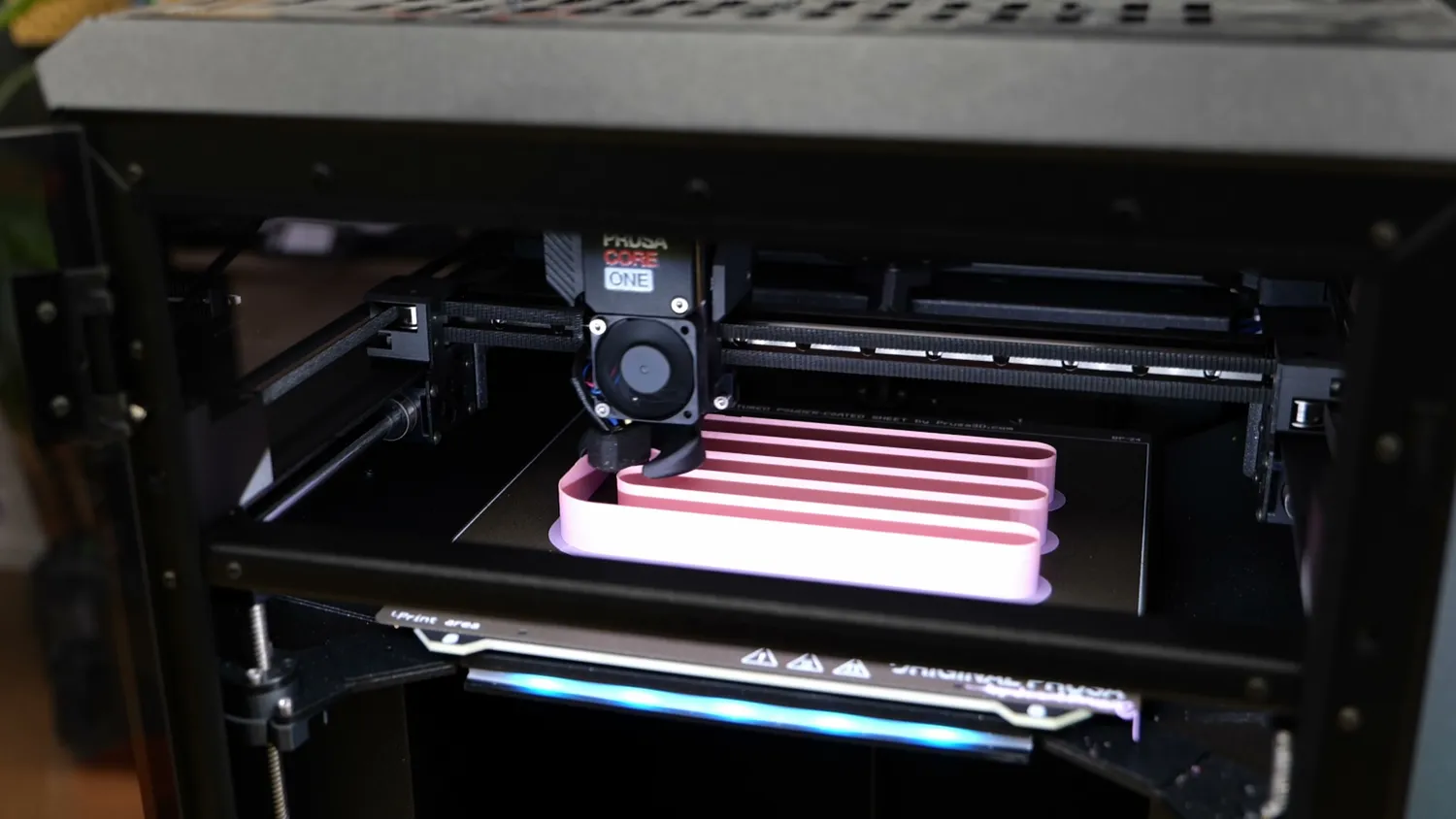
Maximum flow test print
The next obvious one is maximum volumetric flow.
I have previously used a separate load-cell test rig to study extruders, nozzles, and filament materials. When the extrusion rate increases, the required force also rises.
At some point, the hotend can no longer melt and move the material reliably. The force response becomes unstable, rises sharply, or begins deviating from its expected behavior.
With a load cell already built into the printhead, the printer could perform a flow-rate sweep automatically.
It could begin at a low extrusion rate, gradually increase it, and determine the maximum stable flow for that exact combination of material, temperature, nozzle, and hotend.
That would be far more useful than relying on one generic maximum-flow value for an entire material profile.
This test is also already implemented in my web-tool.
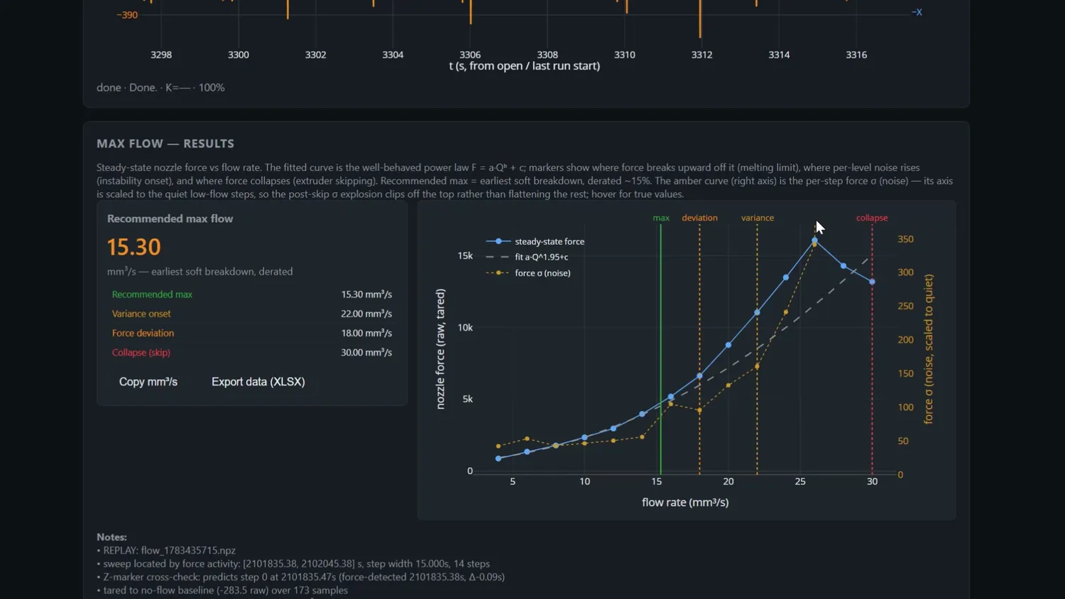
Max flow results in the web tool
Because the Prusa load-cell arrangement is sensitive not only to vertical force but also to lateral loads, the nozzle could potentially probe geometric reference features on the print bed.
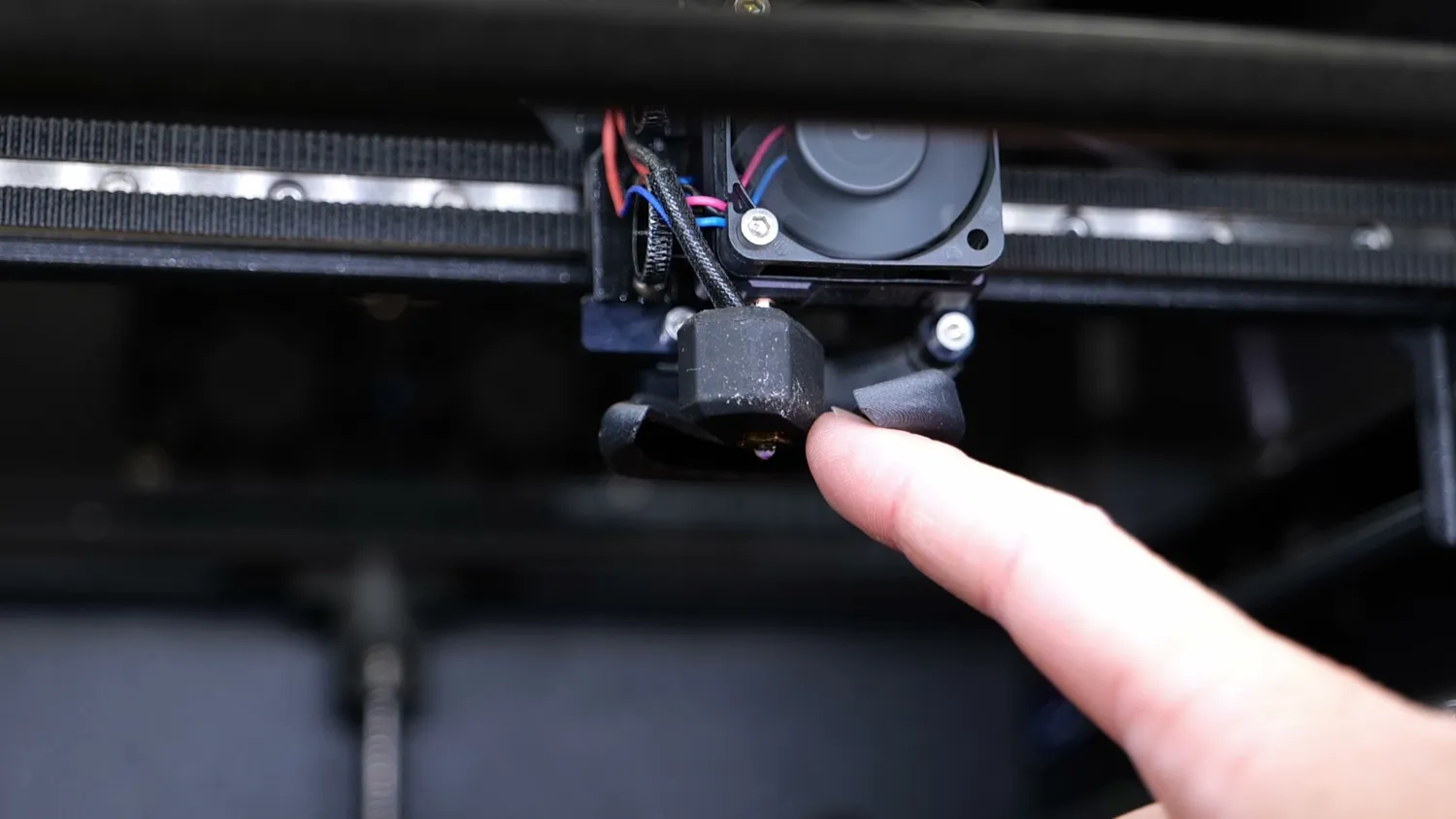
The load cell also senses lateral forces
In principle, this could allow the printer to measure whether its X and Y axes are truly perpendicular and detect skew after the CoreXY belts have been adjusted.
Prusa already uses lateral nozzle contact when calibrating the tool positions on the XL, so the basic capability is there.
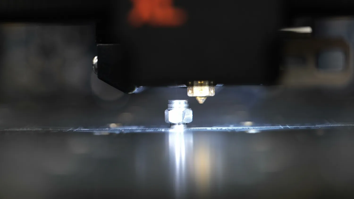
The Prusa XL probes with the nozzle
I would not claim that all of these ideas can be implemented reliably tomorrow. But they demonstrate how much information may be hidden inside a sensor that is currently used almost exclusively for bed probing.
And this leads to a much bigger topic: process monitoring.
3D printers are increasingly being used for real production parts, but our quality control is still surprisingly primitive.
Most of the time, we look at the outside of the finished part and decide whether it appears acceptable.
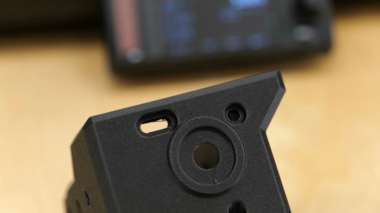
Visual inspection only shows the outside
But an internal extrusion defect can cause structural or functional failure even when the exterior looks completely fine.
Imagine receiving a process report after every print.
The machine could confirm that nozzle and bed temperatures remained inside their specified windows. It could report whether unusual nozzle forces were detected, for example at a crash, whether the extrusion response remained stable, and whether there were signs of a collision or partial clog.
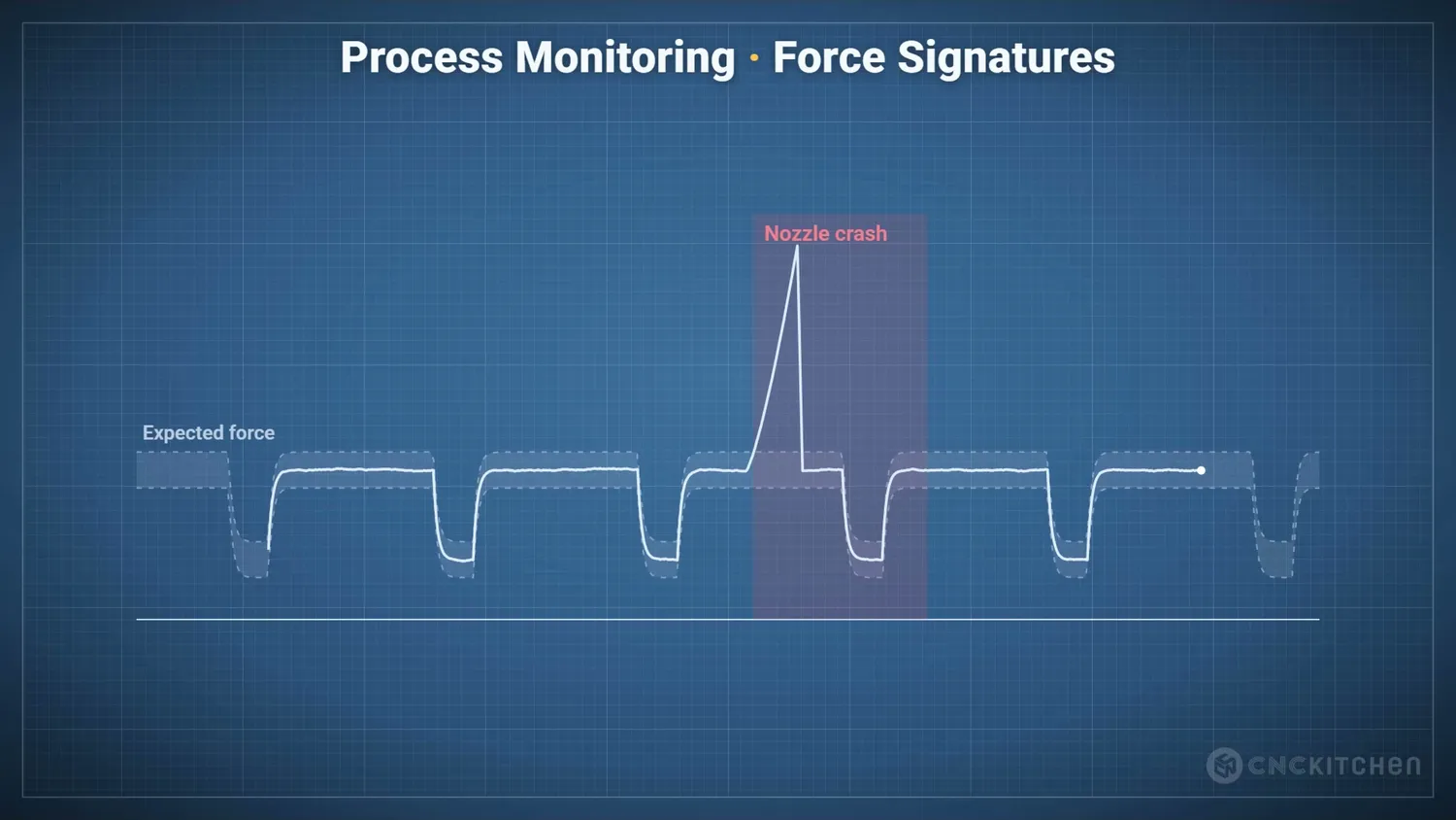
A nozzle crash in the force signal
A nozzle-force sensor alone cannot guarantee the quality of a finished part. But combined with the data the printer already collects, it could provide far more insight than we currently get.
This is why I think these sensors are still extremely underutilized.
Prusa has included a nozzle load cell in its machines for more than three years, but its main job is still simply to touch the build plate.
My relatively simple experiments show that the same hardware could potentially calibrate the material and monitor the printing process.
Fortunately, there are already other projects moving in this direction.
During my research, I came across bd-pressure from PandaPi3D. It combines a nozzle-force sensor with a Klipper plugin that performs automatic Pressure Advance calibration.
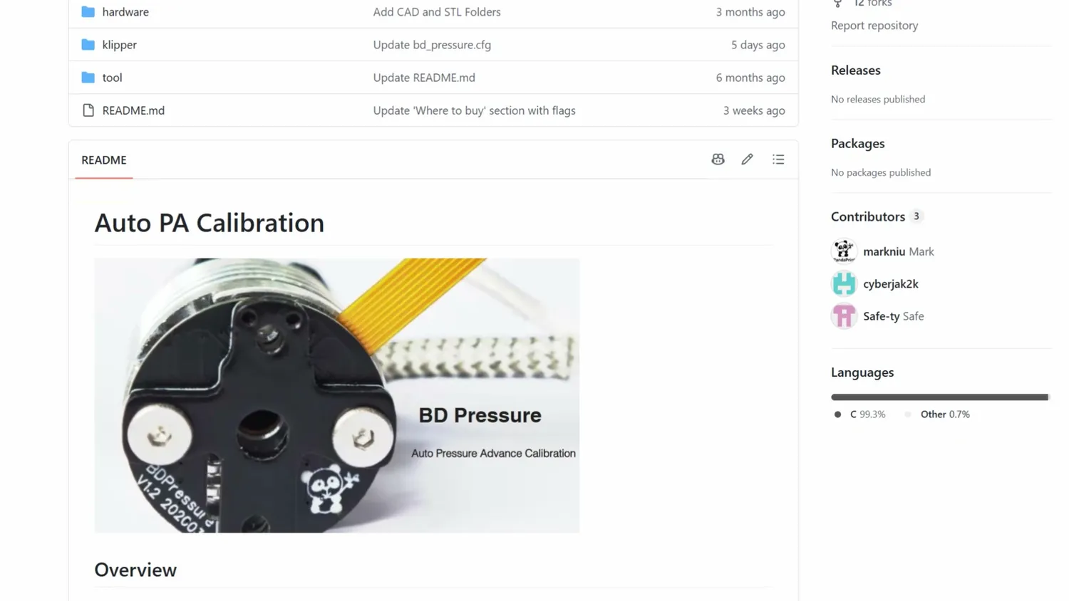
bd-pressure by PandaPi3D
There is also the Amplify Hotend, which is expected to come to market later this year. It uses Revo nozzles and includes an integrated load cell, so it may be able to use a similar approach.
And then, of course, we have the Snapmaker U1, which already performs a force-based automatic calibration, even though part of the evaluation algorithm is not visible in the publicly available code.
So the concept clearly works.
The remaining challenge is making it reliable across different printers, hotends, nozzles, temperatures, and materials.
The patent situation
Finally, there is the question of why automatic material calibration is still not more common.
Initially, I assumed that manufacturers simply had not invested enough time into developing a robust algorithm.
But during my research, I also came across several patents from Bambu Lab.
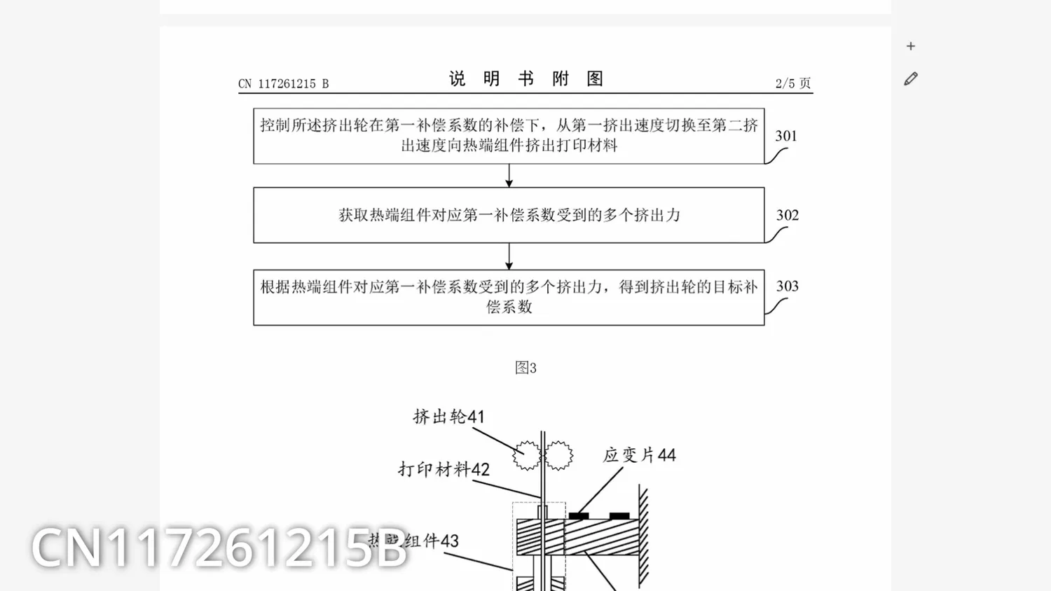
Bambu Lab patent CN117261215B
A quick disclaimer: I am not a patent lawyer, and none of this is legal advice.
For the camera- or pattern-based calibration approach, Bambu Lab appears to have active patent protection in China, the United States, and Europe.
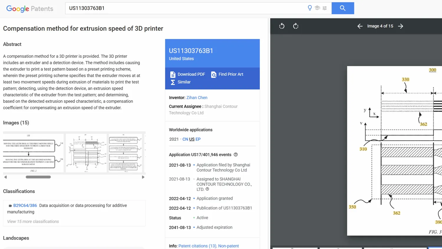
US patent for pattern-based calibration
That means another manufacturer may not be able to simply recreate the X1 calibration system without considering those patents.
The force-based approach appears to be slightly different.
The method is patented in China, but the related international application currently, as of July 2026, appears not to have been pursued successfully in Europe.
I don’t know why, and the legal situation may be more complicated than simply searching for one patent family.
But it leaves at least some hope that similar force-based calibration systems could appear in more machines or eventually become a standard feature in open-source firmware such as Klipper.
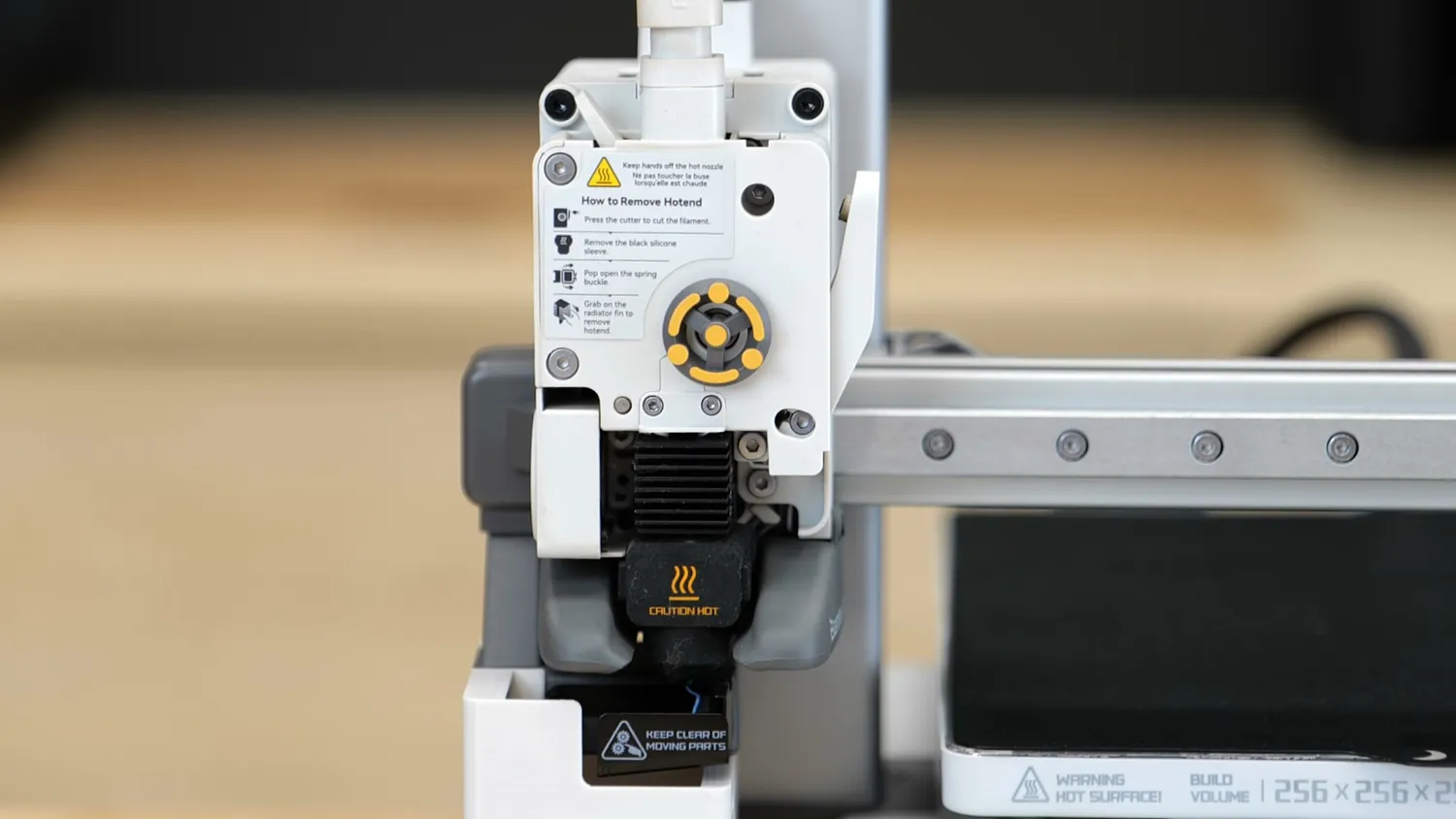
Snapmaker U1 toolhead
Patents are always a controversial topic. Bambu Lab has a legitimate commercial interest in protecting the technology it developed, while the rest of the industry would obviously benefit from wider access to automatic calibration.
I’m not going to resolve that debate here, but I will continue following the patent situation on this specific topic and let you know if anything changes.
For me, the most important takeaway from this experiment is that the necessary hardware may already be inside many of our printers.
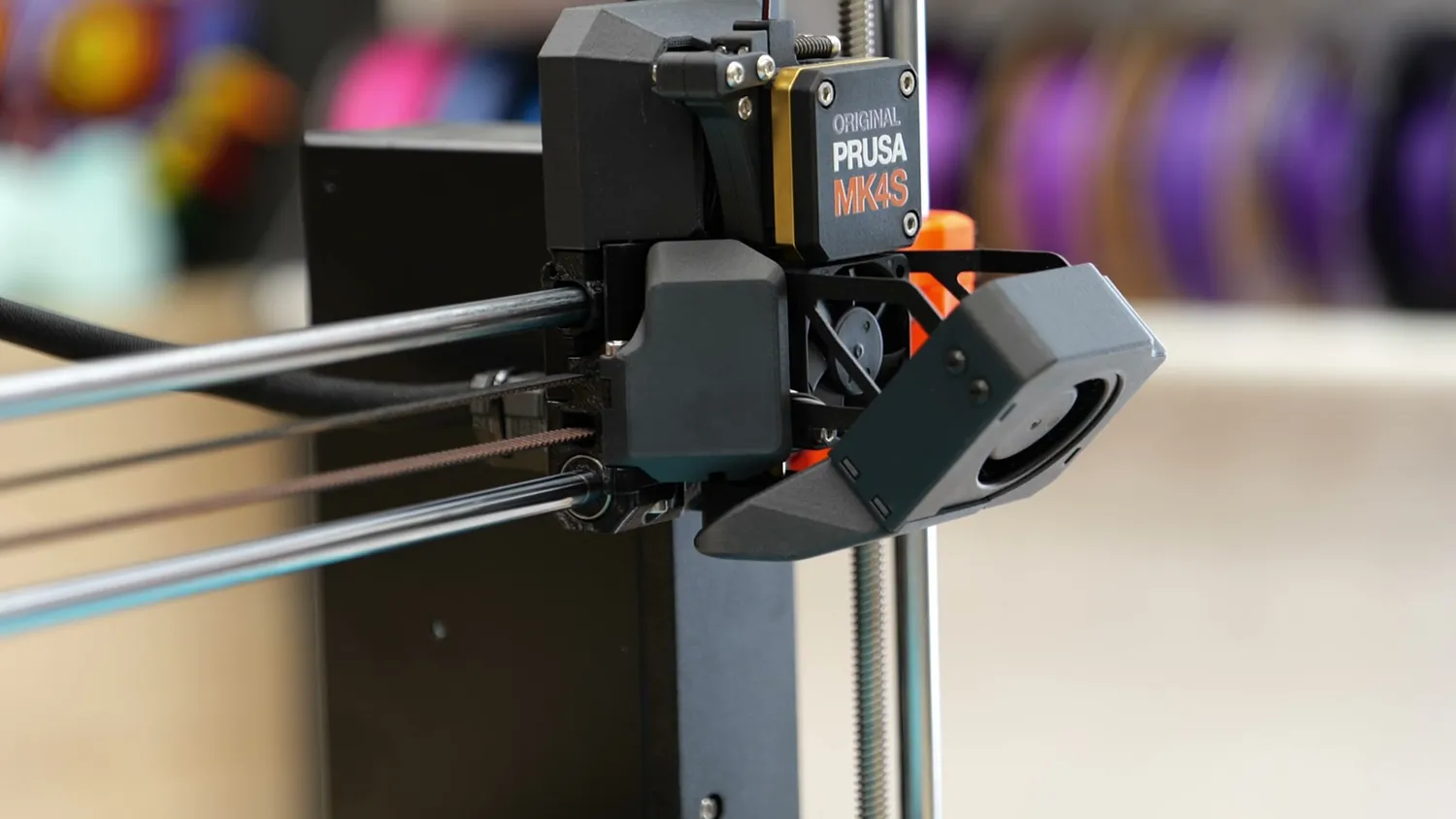
The Nextruder load cell
The load cell used to touch the bed can also observe what happens during extrusion.
With the right test and the right algorithm, it can estimate Pressure Advance, potentially determine maximum flow, and provide valuable information about the printing process.
My current web-based tuner is not perfect, and this functionality would ultimately work much better inside the printer firmware.
But it demonstrates that smarter software can unlock entirely new capabilities from sensors we already have.
You can find the complete project free and open source on my GitHub.
* Links marked with an asterisk are affiliate links — if you buy through them, I earn a small commission at no extra cost to you. As an Amazon Associate I earn from qualifying purchases. Thanks for supporting my work!