10 Tips for Better 3D Scans (feat. Creality CR-Scan Raptor)
10 practical 3D scanning tips from a summer with Creality's CR-Scan Raptor: markers, resolution vs. accuracy, multi-orientation scans and measuring warp.
TL;DRthe short version
- The CR-Scan Raptor is a hybrid scanner: near infrared tracks on geometry and needs no markers, blue laser resolves far more detail but always needs retroreflective markers.
- Blue laser mode scanned shiny machined aluminium and even a transparent container without any scanning spray, which surprised me.
- Resolution and accuracy are not the same thing: resolution is the smallest feature a scanner can capture, accuracy is how closely the dimensions match reality.
- My DIY ball bar came out at 100.24, 100.25 and 100.22 mm against a nominal 100.25 mm, so around 0.3 mm deviation per meter.
- A 50 cent coin at the maximum 0.02 mm laser resolution looks incredible, but most of my scans ran the 0.15 mm default and still resolved machining marks.
- Flat parts need a third scan linking top to bottom, or the merge looks fine while the thickness is completely wrong.
- Creality Scan bends up the outer edge of every single scan. It is systematic, it shows up as seam lines, and it is the one thing I really want them to fix.
- Scanning the printed AC cover against its CAD showed over 6 mm of warping at the worst edges, which is hard to judge by hand and trivial with a scan.
Have you ever thought, man, I’d really like to have a 3D scan of a pickle? We’ll wait no longer because I finally did! I had such a great time using Creality’s new hybrid 3D scanner that now has a super powerful blue laser mode that I started scanning everything! If you already have or think about owning a 3D scanner, then this article is right for you because I share 10 essential tips on how you can get great scan results as well! Let’s find out more.
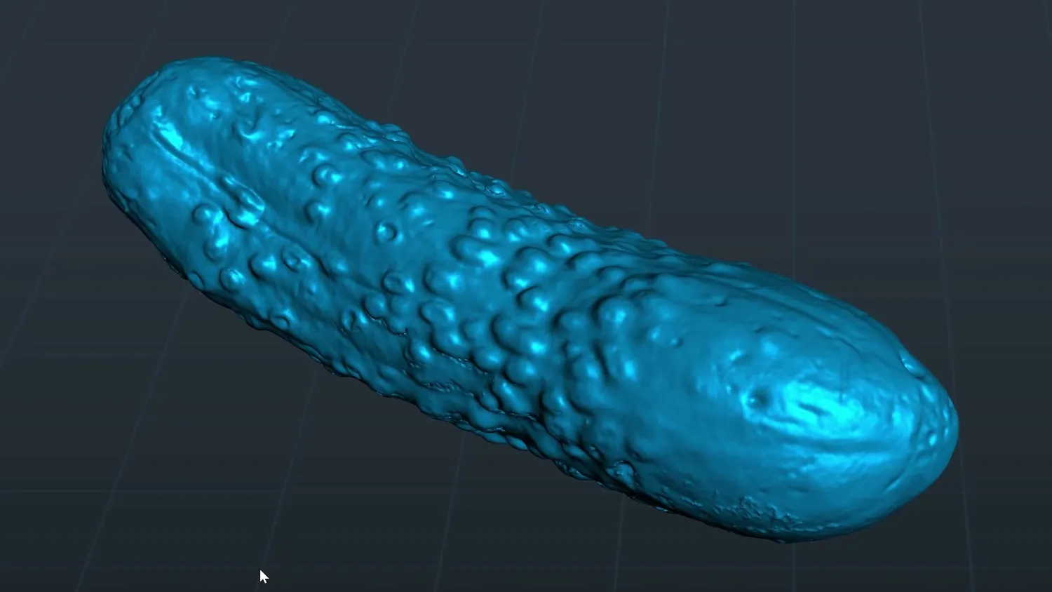 The pickle, scanned in blue laser mode
Reverse engineering a portable AC
For over a year now, I wanted to do one particular 3D scanning project and when Creality recently reached out to sponsor a video using their brand-new Raptor 3D scanner, I was super stoked. I love my studio yet during summer it can get horribly hot in here due to sub-optimal roof insulation. I have a monoblock portable AC yet it’s one of these super inefficient one-hose units. So I wanted to convert this to a two-hose unit yet not by slapping a couple of foam board panels around the condenser intake but design a proper 3D printed air inlet. Since this is not all right angles and there are a couple of holes for the cover to grab into around, I thought this is a perfect opportunity to show how a 3D scanner is super useful for reverse engineering. So I unscrewed the intake screen and prepared the scanner for use. Have you ever used a 3D scanner for your project? What type did you use and what tips can you share for getting the best results?
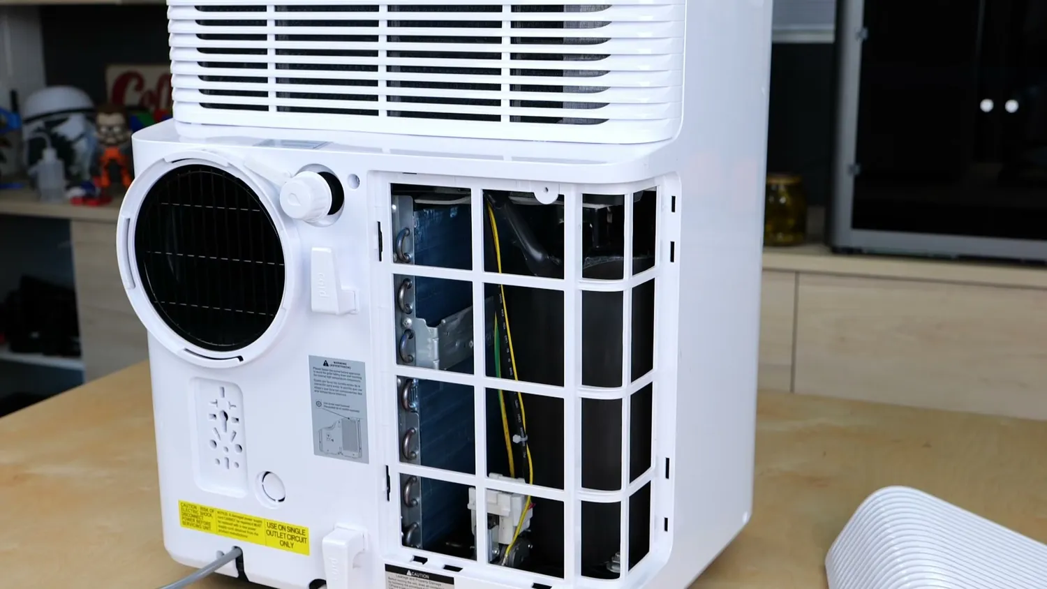 The condenser intake behind the screen
The CR-Scan Raptor
Creality’s Raptor is very different from their other scanner lineup and also other consumer-grade 3D scanners. It costs almost double as their other top-of-the-line structured light scanner but it also comes with one unique feature! Creality calls it a hybrid scanner at a significantly lower price than other hybrid systems on the market. Hybrid, because it can scan in conventional Near Infrared Mode as well as in the usually very expensive Blue Laser Mode. I had a ton of joy using the scanner and was blown away by the ease and details of scanning in laser mode. I also uploaded a couple of scans so you can judge the quality yourself!
🔍 Get the Creality CR-Scan Raptor: https://geni.us/CR-ScanRaptor*
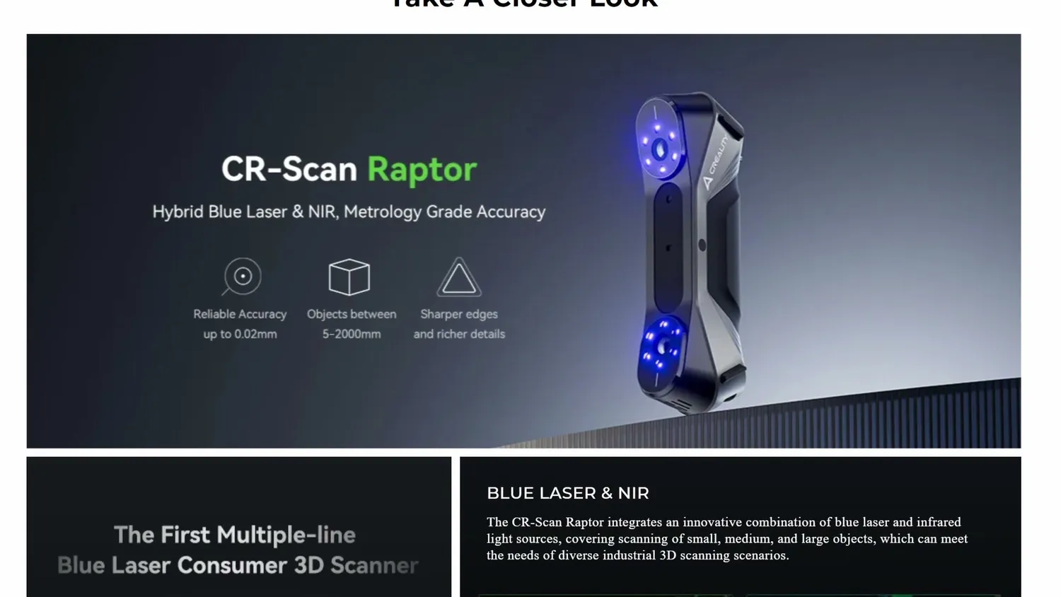 Hybrid: blue laser and near infrared in one
Tip #1: Use the right technology
So the Creality Raptor has two modes. Blue Laser and NIR. But what’s the right mode and what’s the difference between them? Let’s start with the Near Infrared Mode, which works very similarly to a face ID camera by projecting points on your model and triangulating their distance. Its biggest advantage is that you can do a 3D scan without any tracking markers because it stitches frames together using geometric features. Using markers is possible and usually the way more stable solution, but working without them is handy because you can scan objects without any preparation, like, for example when I scanned my Vespa for some repairs or if you scan people. The CR-Scan Raptor also has 3 different scanfields in NIR from 200 mm to over 400 mm diagonal to easily scan small as well as big parts. The small scanfield gives you more details and the bigger ones speed up the scanning process and, especially in geometry mode help with tracking because more features are usually within one shot. The laser mode also has a scan field diagonal of around 20 cm but due to the very thin laser-lines that are projected, it captures significantly more details than the same scanfield in NIR mode which becomes very obvious when we compare two scans! Yet this comes at a cost. The laser mode requires that you use these retroreflective scanning points and since the scan field is relatively small you sometimes need a lot of them, especially at bigger parts. I’ve been using professional structured light scanners for many years now and one of the things I wanted to highlight in this article was surface preparation with contrast sprays to get good results. Yet I was really blown away by the performance of the blue laser mode. I scanned a ton of different parts and never had to prepare them with my scanning spray, even the machined aluminum part or parts with a lot of contrast. The quality of the results does improve if you spray them but most of the time this step isn’t necessary, which is a huge benefit of this technology! In the end, you always need to think about which mode is the right one for you. If you want to scan people or faces, NIR is the way to go. If you don’t need to resolve very small details, NIR might still be the more efficient option due to the geometry tracking feature, yet if you want to scan very detailed parts, even if they are shiny metal, the laser mode is the way to go at the cost of the markers that you need to use. And whereas most other consumer 3D scanners only use the structured light approach, the Raptor gets you both in one package!
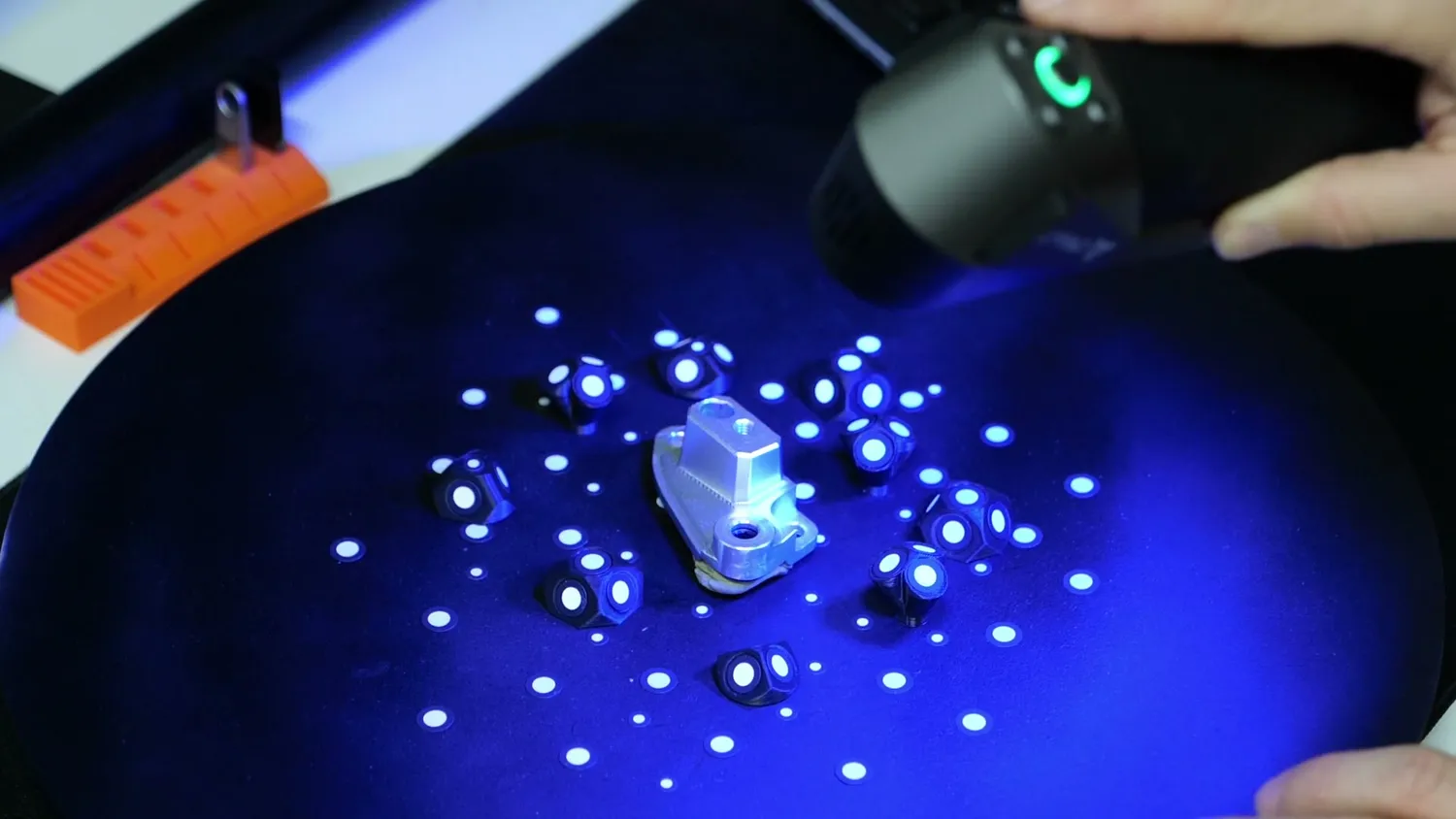 Blue laser needs markers, but resolves far more
Tip #2: Use enough markers
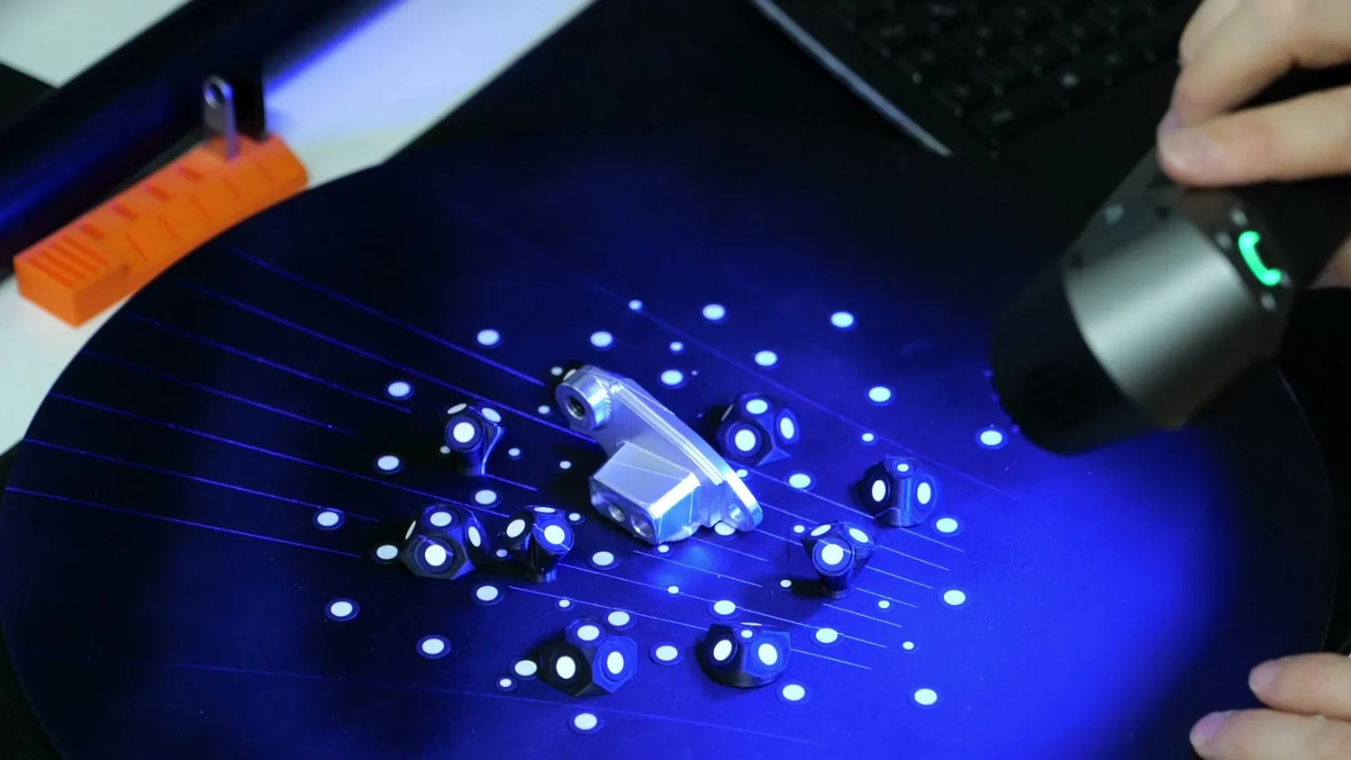
So, let’s prep my AC. Even though this may be a bit overkill, I wanted to scan the AC in laser mode. So the first thing we need to do is to attach these retroreflective points to the area that we want to scan. They are used to align the individual frames that are generated during scanning to each other in order to create the 3D model. For a bigger part like my AC, you directly stick them to the object that you’re scanning because we need at least 4 overlapping points always in frame so that the alignment of the scans properly works. The thing that is important is that you should not aim for a regular placement. The scanner resolves its position in space by matching unique points with each other, so the placement should be random. For smaller parts, I have a scan table which already has a ton of points attached so I don’t use and waste a ton. I also have a bunch of these movable makers with a magnet that I can place around the part. Shoutout here to the Thai channel Payo, who has awesome videos around 3D scanning and who designed some of these models. Marker points are best recognized if you look at them perpendicularly, so if you want to scan a part from the side, the ones on the scanning table might not be recognized. The targets put them at an angle, so you don’t lose tracking as easily. And they are not only handy on my scan table but you can also place them on bigger parts and since they have a magnet, they stick at any angle on steel.
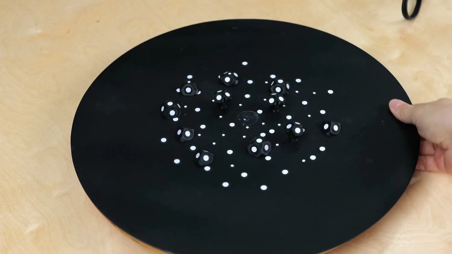 Random placement is what makes the alignment work
Tip #3: Use the proper hardware
The handheld scanner can’t be used autonomously, needs power from a wall adapter, and requires a connection to a PC or Mac that runs Creality Scan. Due to the amount of data that’s being processed, you need a pretty powerful machine for that. I initially started with my travel ultrabook which doesn’t have a dedicated GPU, and I really struggled to get a smooth scanning experience. Switching over to an M3 Macbook Pro quadrupled my FPS and I got a flawless scanning workflow. I also scanned some of the parts on the desk using my editing workstation which also didn’t have a problem running the software. So make sure your hardware is also sufficient if you want to dive into 3D scanning.
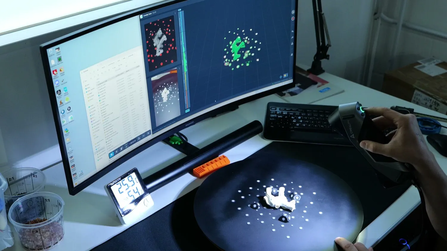 Scanning small parts on the editing workstation
Tip #4: Use the right resolution for your project
Within Creality Scan, you first select the mode that you want to use. I started in the blue laser mode and selected a suitable resolution. You should always select a resolution adequate to the size of your object to limit the amount of data that’s being generated. So, if you have a big part, you would rather use a smaller resolution. Smaller resolution doesn’t necessarily mean worse scan accuracy, and I’ll touch on that later.
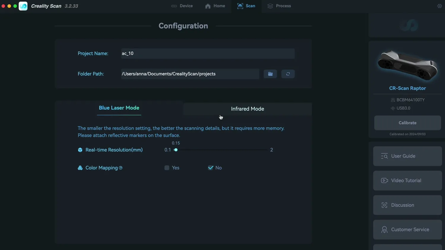 Mode and resolution get picked before scanning
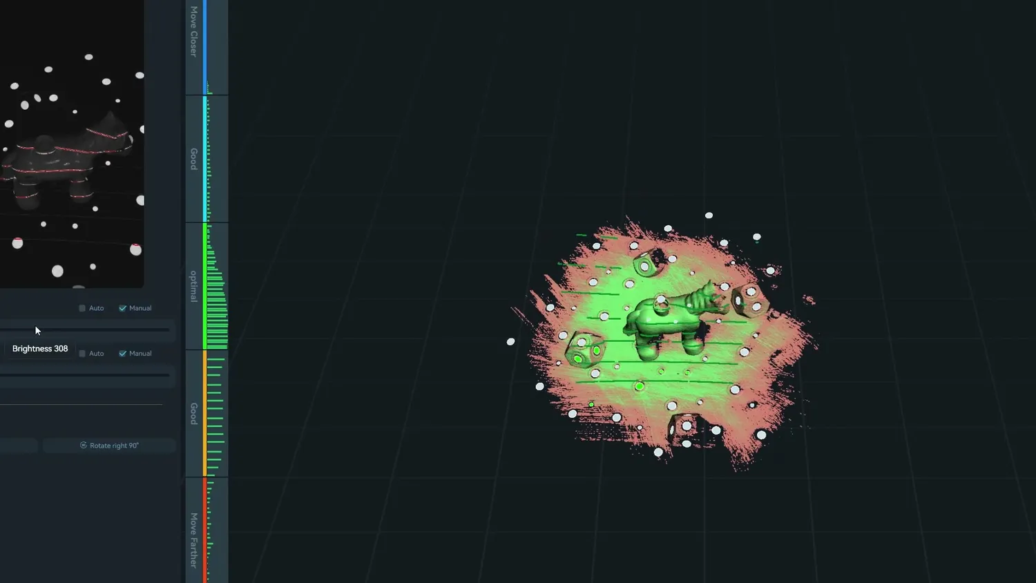
And then it was time for scanning. As soon as the cameras see enough tracking points, the lasers turn on, and you can start scanning. In Blue Laser mode you pick up depth data from the 7 lines that are projected on the part, so by swiping the scanner, you start to capture the surface. The scanner should always have an optimal distance from the part that you’re scanning, as indicated by the bar on the left but also by the LED button on the scanner. This is really handy if you don’t want to constantly focus on your screen but rather the part you’re scanning. If it’s blue, you’re too close, green is optimal and once it turns orange or red, you’re too far away. Depending on the amount of markers you used, the scanner might regularly lose tracking and stop recording data, so you need to go back to a known location and continue from there. Scanning itself is really quick, and it only took me a minute or two to capture the back of the AC. Scanned areas usually start with a red hue when there is still not enough data available for the resolution you selected so you’ll need to continue scanning your part until most of the surfaces turn green, otherwise the scan results will be non-optimal.
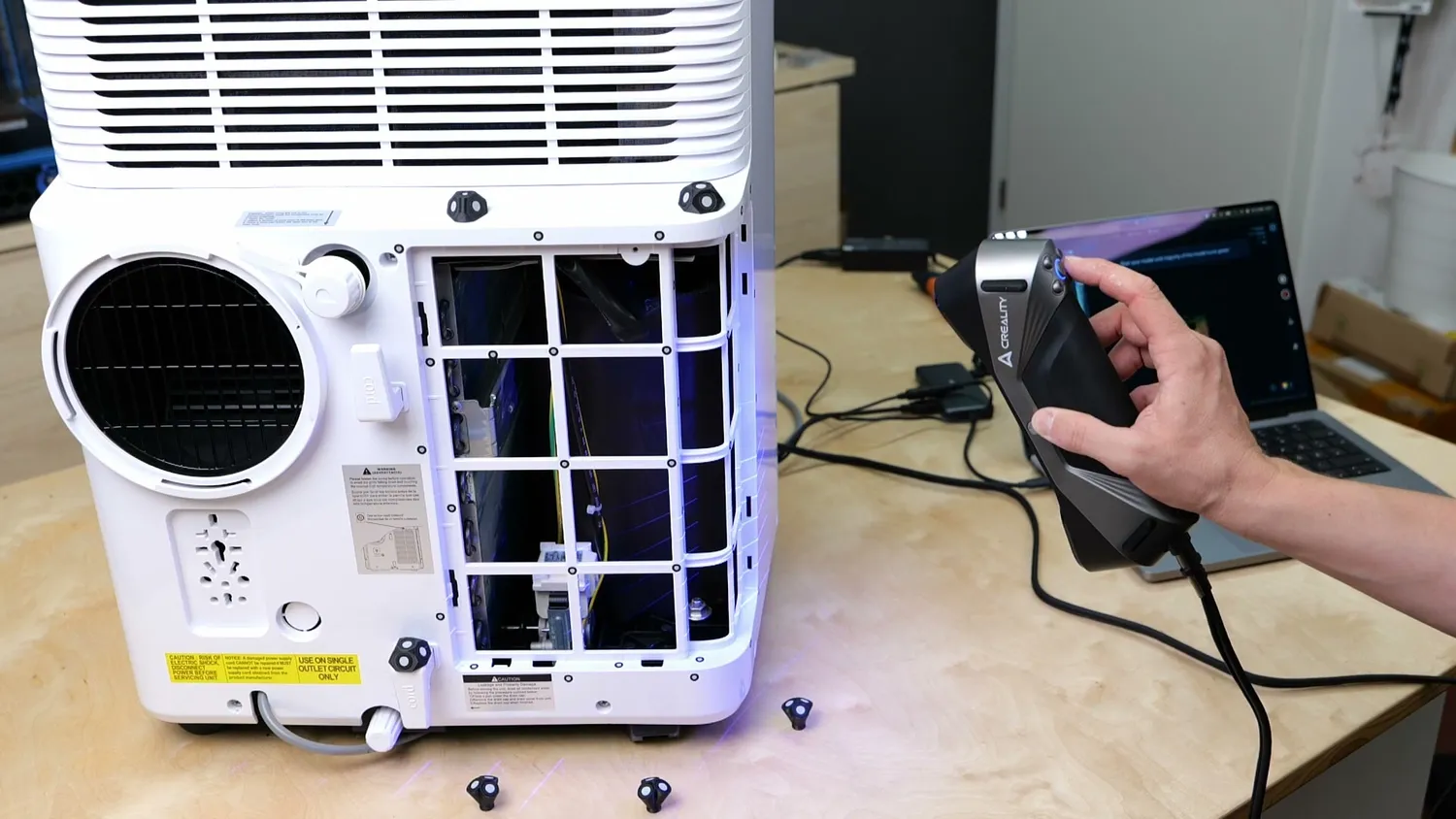 Seven laser lines sweeping the condenser intake
After finishing the scan the data needs to be processed. The scanner itself doesn’t directly generate an STL model as we know it from 3D printing. Even though it looks like a surface if we zoom out enough, a 3D scan is, at first only thousands or even millions of points called a point cloud that needs to be further processed. So I started by cutting away all the parts that I didn’t need for my design process, which included some of the internals of the AC as well as part of the frame. This reduces the amount of data that’s being processed and just makes everything faster. The first processing step is optimization, which fits regularly spaced points over our point cloud. The default settings usually work well, but you can tweak them a little depending on the resolution you’re aiming for. Once this is done you can further remove some unwanted data and then go to mesh generation. This will fit a triangle mesh over the points that you can then export as an STL or OBJ. Scans can have holes, where the scanner wasn’t able to pick up points and Creality Scan allows you to close them automatically if they are small enough. “Closure” even allows you to create a watertight STL, which might be necessary for 3D printing, yet this is, of course, only possible if you scanned most of a part and it doesn’t make sense or is even necessary for the back of the AC we scanned. This finally reveals the true details of the scan, which you can see when you zoom in. The scanner was able to pick up a ton of details even though I didn’t use the maximum resolution it is capable of. Don’t worry, we’ll do a high-resolution scan in a bit. The only artifact of the laser mode I was able to see on this and many of my other scans was a slight stripe pattern on the part. It’s noticeable yet subtle and can even be smoothed out with further processing. I then exported an STL, which can be imported into any current CAD software to be used as reference geometry to design around.
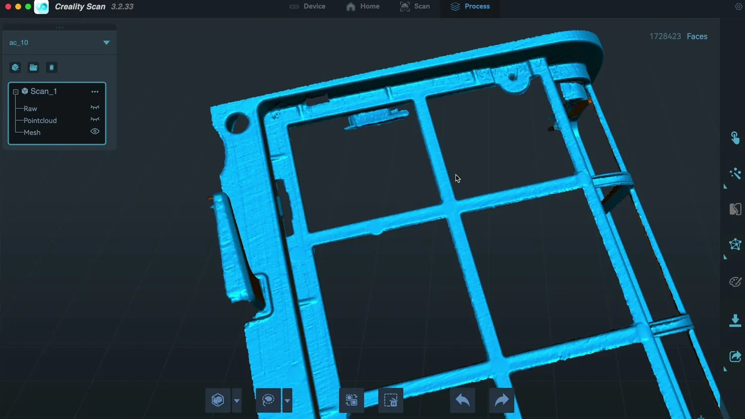 The point cloud, meshed into an STL
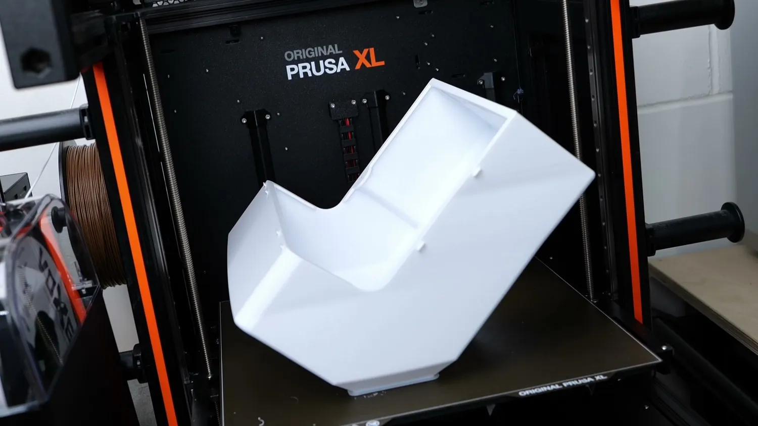
So I first aligned my scan within Autodesk Fusion and then started designing the box with the 125 mm hose adapter and small pegs that will help keep it in place when installed. Using the scan as a reference was great for getting a perfectly fitting shroud, hopefully on the first print. I then exported the STL, loaded it into my Slicer, and started printing it in PETG. This took over a day to print, and until it’s finished and we’re able to scan it to check for dimensional accuracy of the print, let’s talk a bit about accuracy and resolution of 3D scanners in general because this is a topic often misunderstood.
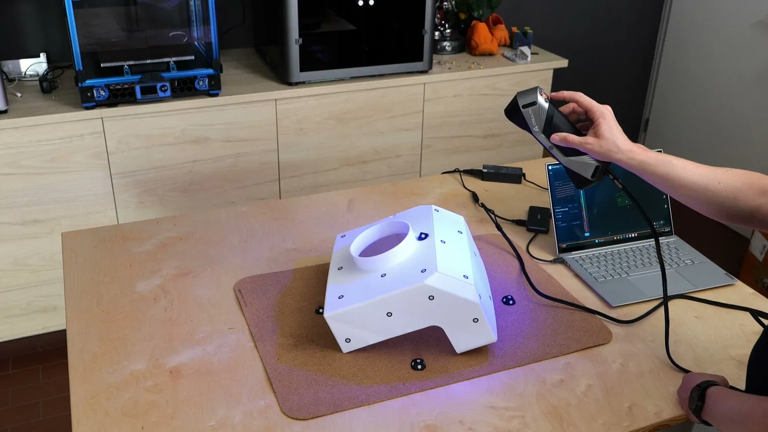 The finished cover, later scanned to check it
Tip #5: Understand the difference between resolution and accuracy
A specification people always look for when browsing 3D scanners are resolution and accuracy. Yet many mix them up or even think they mean the same thing. Resolution refers to the level of details a scanner can capture, specifically the smallest feature size. Accuracy on the other hand is the measure of how closely the scanned data matches the actual dimensions of a part. Compare that with the nozzle size of a 3D printer. The nozzle diameter defines how fine of a detail you can print, but your motion system or your steps/mm can be totally wrong leading to a part with a lot of details but wrong dimensions. If your motion system is perfectly calibrated even with a big nozzle, you’re able to print dimensionally accurate parts, but it might miss details.
 Measuring the DIY ball bar with calipers
The Creality Raptor is advertised as having Metrology Grade Accuracy. Even though that doesn’t say a lot and is PR talk, there is something to this. The big advantage of even consumer grade 3D scanners over for example the photogrammetry that you can do with your phone is that they scan to size. A photogrammetry scan gets exported at basically a random scale and you need to size it to have proper dimensions. 3D Scanners on the other hand usually get calibrated using calibration plates. These are often panels with dots printed on them, which look very similar to our scan markers. Whereas with cheap scanners these can come simply on paper or on a bit of acrylic the Creality Raptor scanner comes with one, that’s made from glass. This makes it very stable in size due to loads or temperature changes. The positions of these dots are measured very precisely in factory and stored as a QR code on the back of the plate. So in regular intervals, you’re required to calibrate the 3D scanner by pointing it at this calibration plate at different angles, which enables the software to calibrate the cameras, the line laser, and even the IR projectors to reach maximum dimensional accuracy.
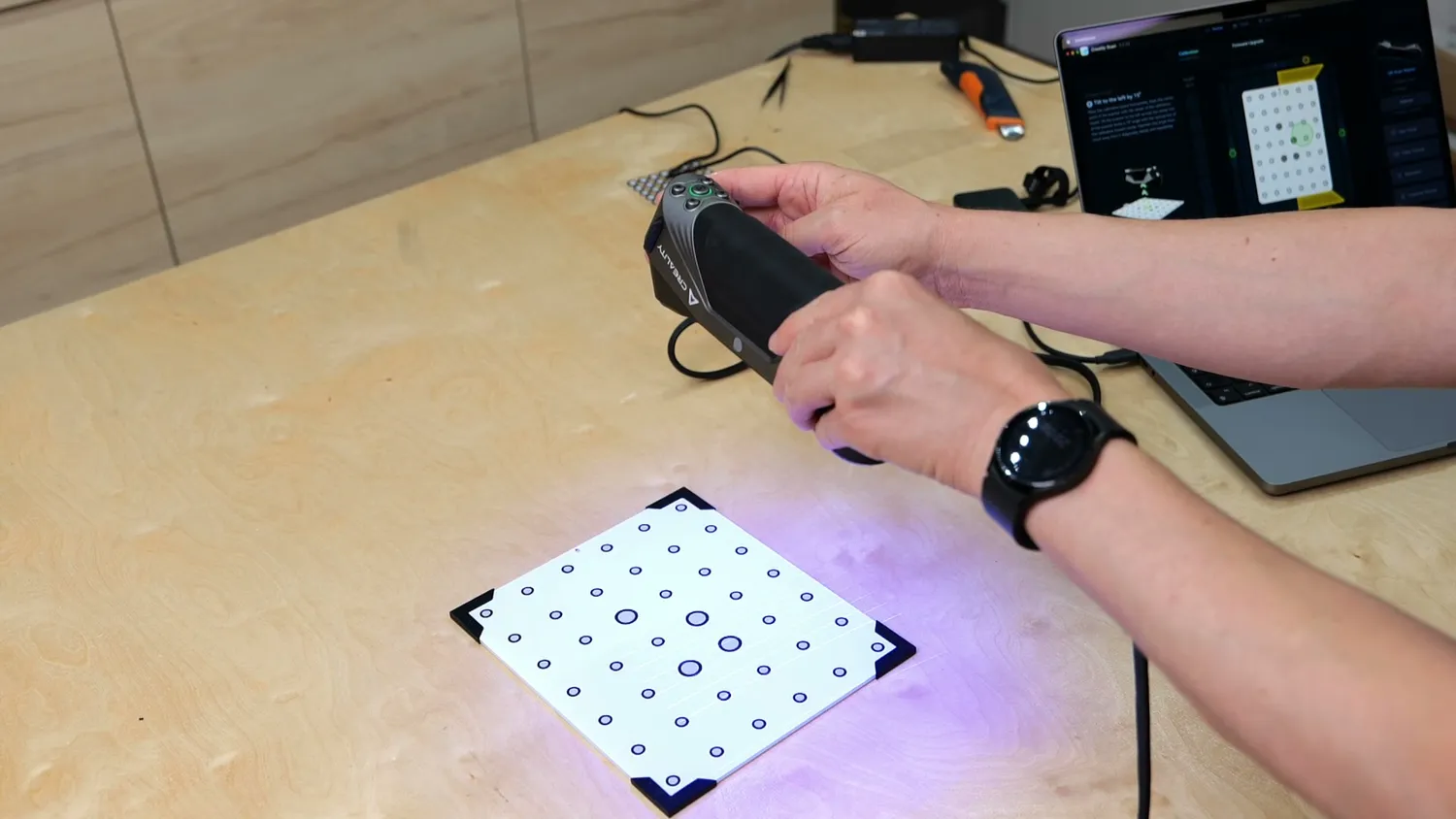 Calibrating against the glass plate
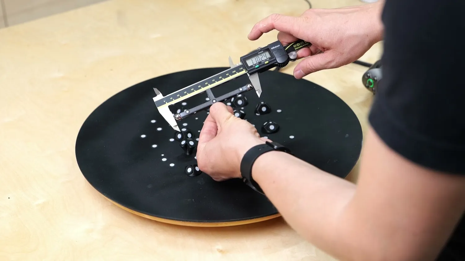
But how accurate is for example the Creality Raptor? There are several ways to check that. One common way in 3D scanning is using a calibration standard, which is often two spheres connected by a bar in the middle. You can purchase these ball bar standards with a certificate that tells you very precisely the distance between the center of the spheres. I didn’t have one so I built myself a very crude DIY version with two 10mm ball bearings and a carbon fiber rod between them. I can measure the outer distance with my calipers and then subtract twice the radius of the balls to calculate the distance between the centers, which was in my case 100.25 mm. I then scanned my DIY ball bar with the Raptor, and exported the STL which I then loaded into GOM Inspect, which is an amazing software to analyze 3D scans. It used to be free, before Zeiss bought GOM in 2019. Yet with a bit of a Google search you’ll still be able to find GOM Inspect 2018 and 2019 installers. I’ve since built a free alternative for exactly this myself: ScanRuler runs right in your browser, fits spheres, cylinders and planes, measures dimensions and maps deviation against your CAD, and your files never leave your machine. Anyways, within the tool I can fit two spheres around my scanned ball bearings and measure the distance between them. I scanned the ball bar 3 times in 3 different orientations and the measured center distances were 100.24, 100.25 and 100.22 mm. That’s a maximum deviation of 3 hundredths of a mm per 100 mm or around 0.3 mm deviation per meter which makes it in my opinion very usable for reverse engineering and even metrology to some point.
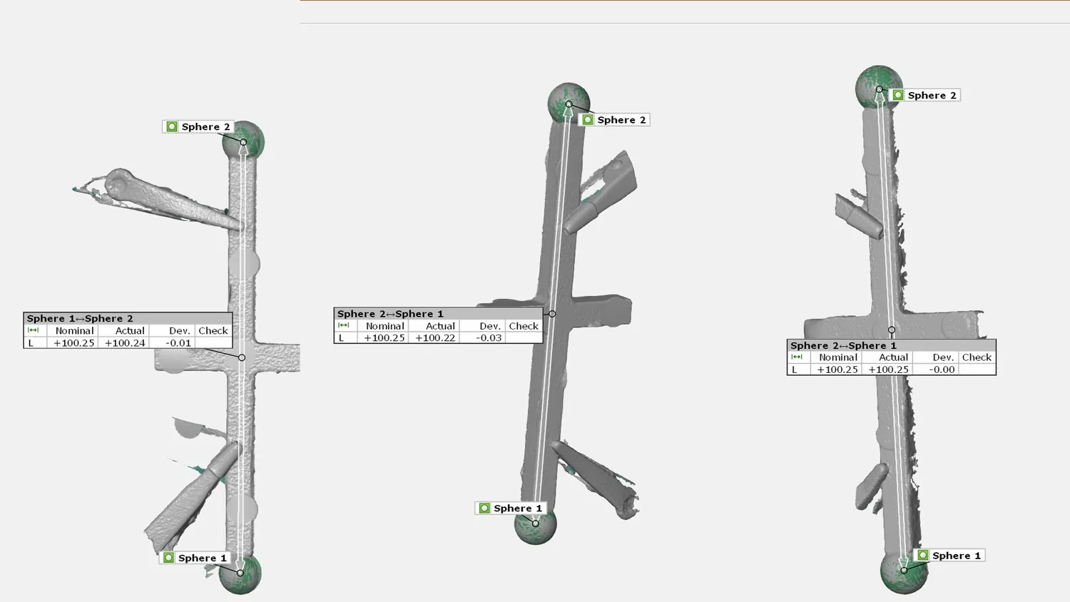 100.24, 100.25 and 100.22 mm across three orientations
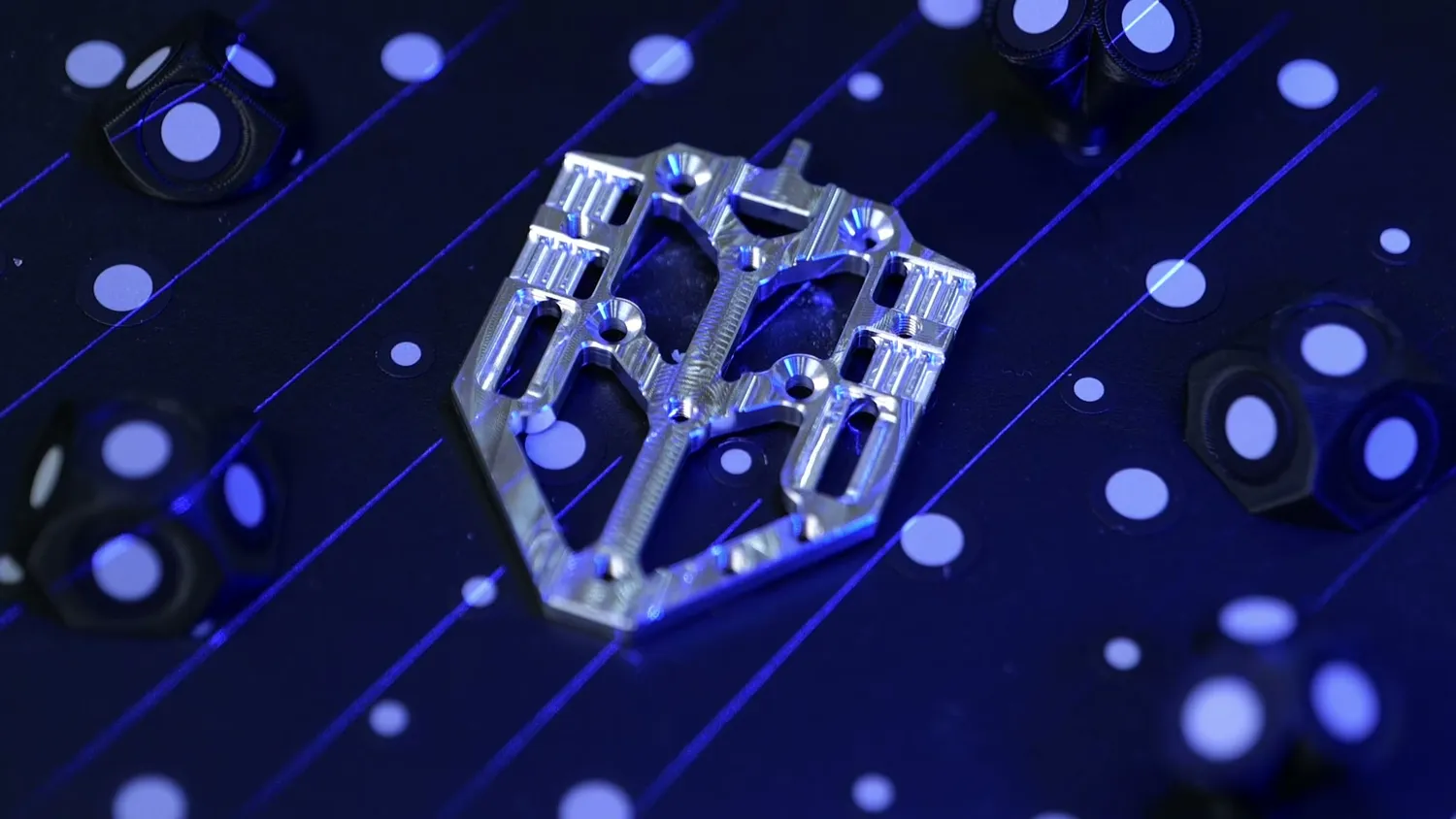
But how about resolution? I did most of my scans in the default 0.15 mm resolution mode which is well enough for most fist-sized parts. I, for example, scanned this machined aluminum part for a colleague. You can easily see the machining marks on the final STL and it’s well-usable for most reverse engineering projects.
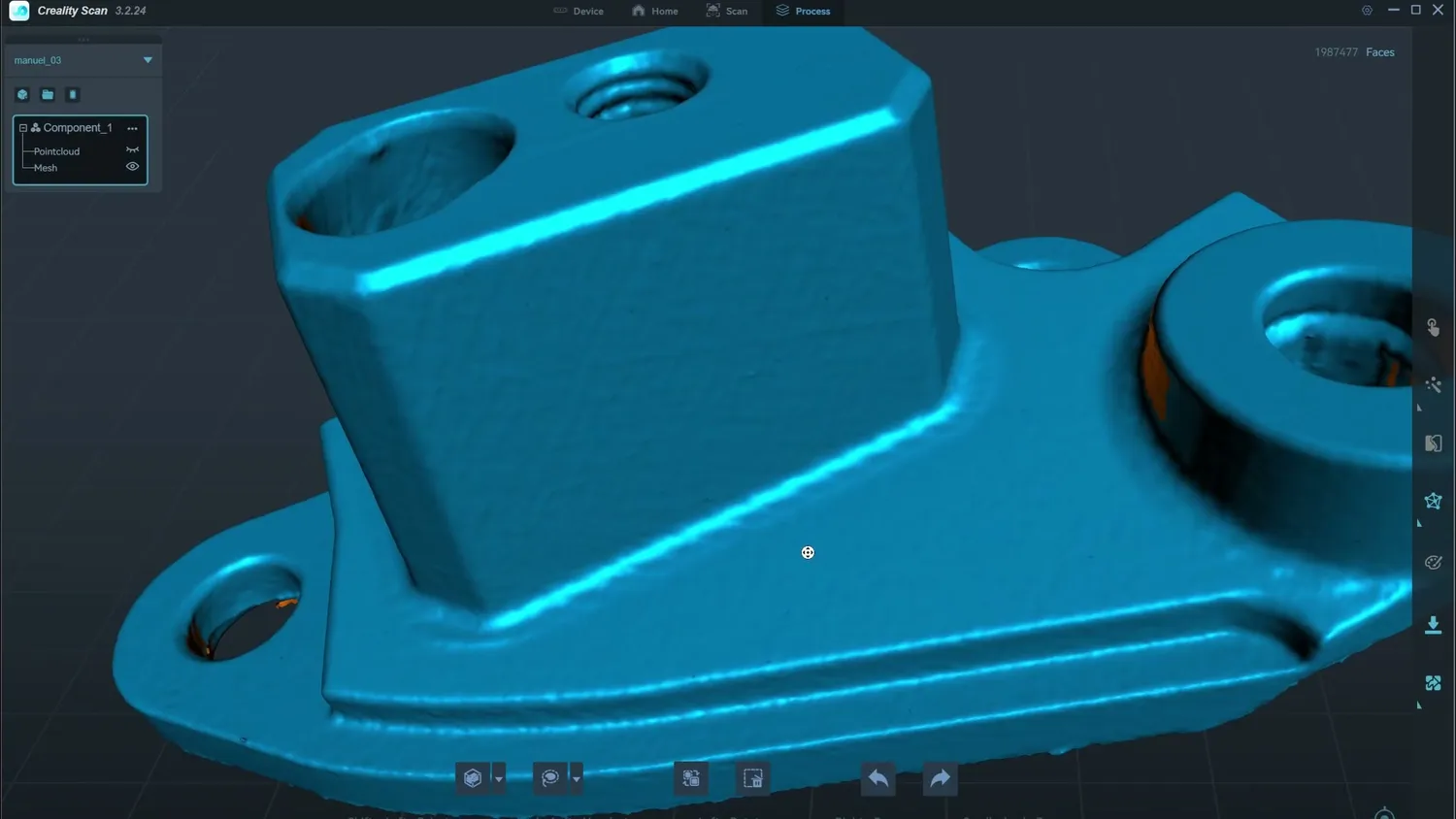 Machining marks resolved at the 0.15 mm default
If you increase the resolution even more, you can resolve an incredible amount of details with the blue laser scanner yet this will also increase the amount of line artifacts you can see on the scan. This Euro coin was for example scanned at the highest 0.02 mm resolution in laser mode which looks incredible and comparing it to the IR mode is almost sad.
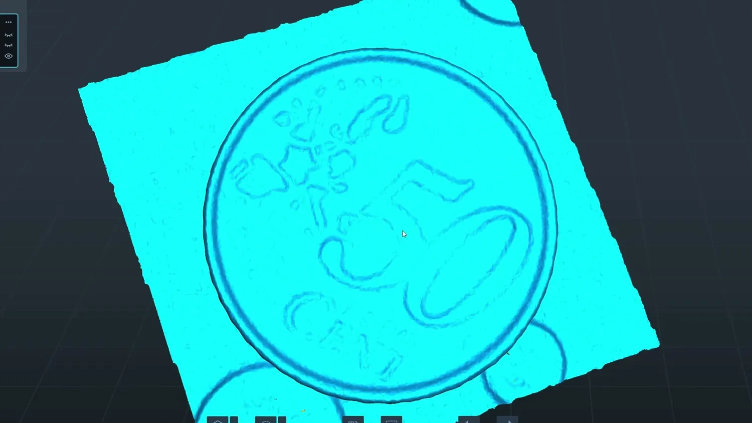 A Euro coin at the maximum 0.02 mm resolution
Tip #6: Multi orientation scanning
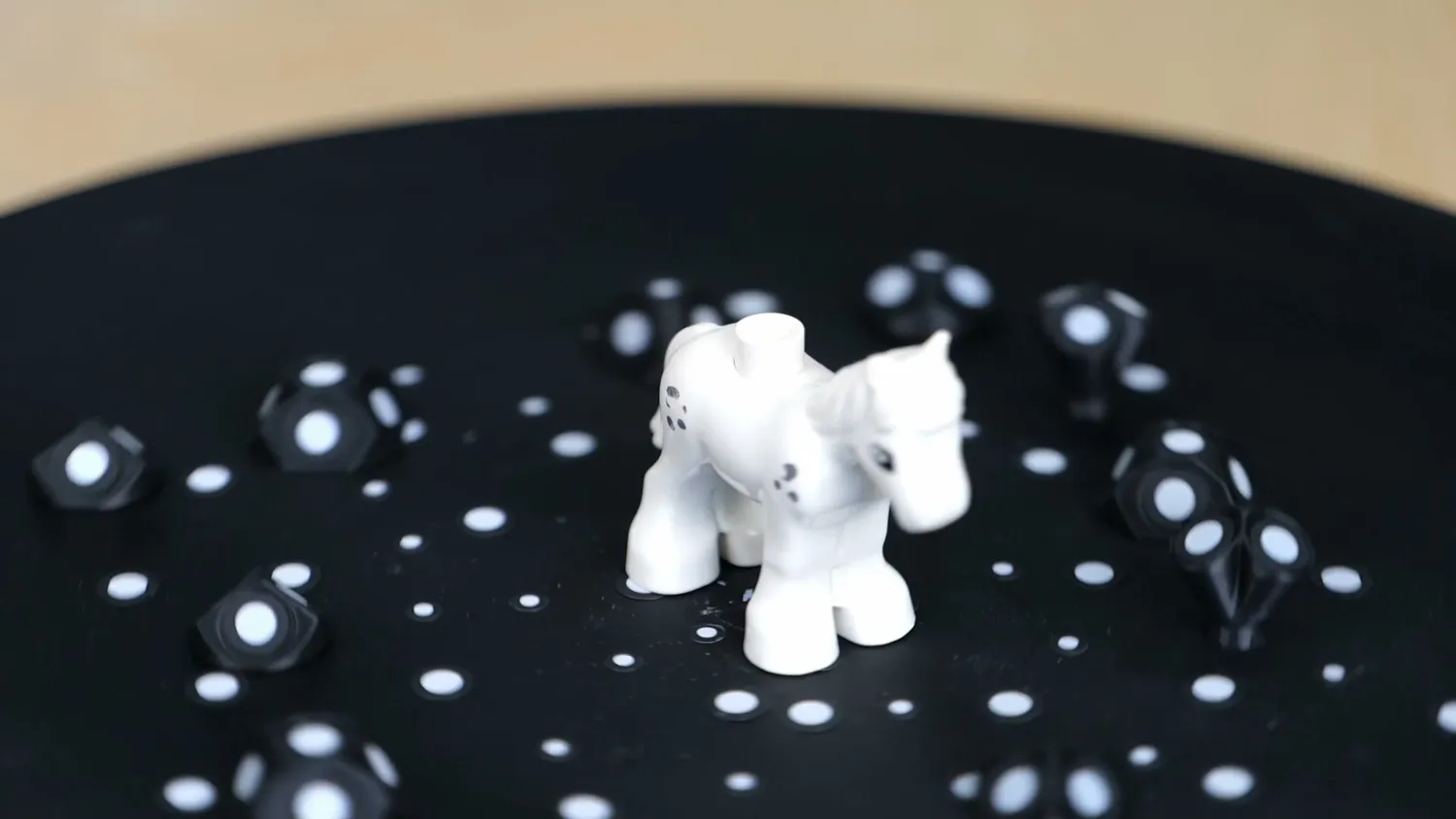
A great example of accuracy and resolution was when I scanned a DUPLO toy of my daughter. I also scanned this in blue laser mode and the amount of details at that size was impressive. I then printed the scan in beautiful Cookiecad PLA and it was perfectly compatible with existing DUPLO parts! Yet this part wasn’t scanned in one take because you can only capture what the scanner can see and illuminate. The underside of parts is often just not visible in the first take, so you need to re-orient the part and scan everything another time. For the horse, I did 3 scans, one standing, one on the left, and one on the right. These are all processed separately and then merged within Creality Scan. If the overlapping areas are big enough and have features, the software can auto-merge the sections. If it struggles, you can do it manually by selecting matching points on two scans.
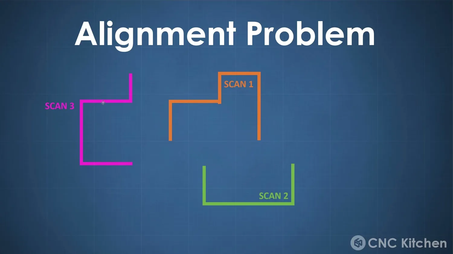
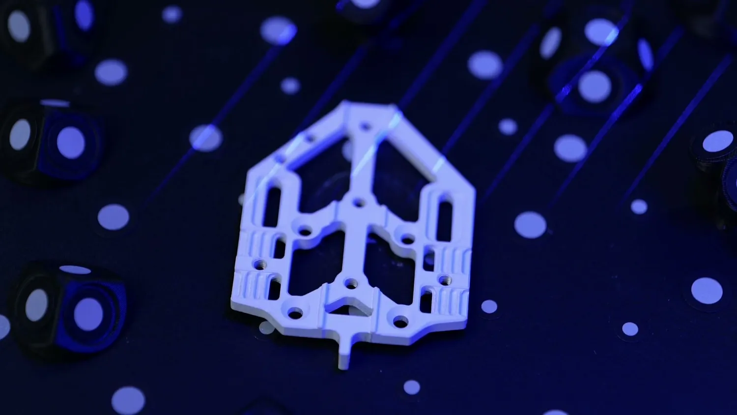
Sometimes, especially on rather flat parts, this can cause a problem if you only scan the bottom and top side. The edge might have enough information to align it within the plane but not enough to put the scans at the right distance. This leads to scans that might look good at first glance but don’t have the proper thickness. This is exactly what happened on the milled aluminum part. With only two scans the thickness was way off, so it’s always a good idea to check your results thoroughly and even take some reference dimensions to cross-check. Solving this is pretty simple because we only need an additional scan that links one side to the other. I did that by placing the part on its side, so I have a scan with the bottom and top surface and the merging or better the alignment of the scans can be done perfectly. This was necessary on the aluminum part, but also for example on the Super Nintendo Controller I scanned.
Tip #7: Secure your parts
Multi Orientation Scanning is key to do complete scans of complex parts. The first orientation is usually clear because you place the part on the most stable surface. Yet if you then angle the parts you can have orientations where the subject can wobble around. If you only work with markers on your part or do geometry tracking that’s not a huge problem. Yet I scan most of my parts on my scanning table which already has tons of markers applied. In such a case, it’s crucial that the part has a fixed position and orientation to the markers during a scan because otherwise, the individual scans won’t line up. To solve that, I usually steal some Playdough from my daughter that I place under my part making sure it stays in place and doesn’t wobble around. If you have flat parts I often even use the modeling clay to get a bit of distance between the part and the table so it’s easier to isolate the part during post-processing.
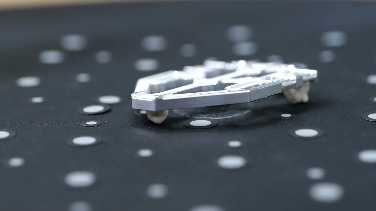 Modeling clay stops the part from wobbling
Tip #8: Create artificial features
While the big shroud still prints, and we have the Playdough at hand it’s worth talking about another use of it besides as a support material. If you like or need to work in geometry tracking mode because you need to scan a bigger part or you don’t want to use markers but your geometry doesn’t have a lot of features for tracking, you can create artificial features on your part. Placing some blobs of modeling clay around and on your part can already be enough that the software doesn’t lose tracking on featureless or repeating parts. If you scan bigger geometries, crumbled-up painters tape is another great and inexpensive option to get great scans. Of course, you won’t be able to capture the geometry at these locations, but a partial scan is often better than no scan at all. And if you need to have a full scan, there is always the option to just place the tape somewhere else, scan again and then merge the two scans in the end.
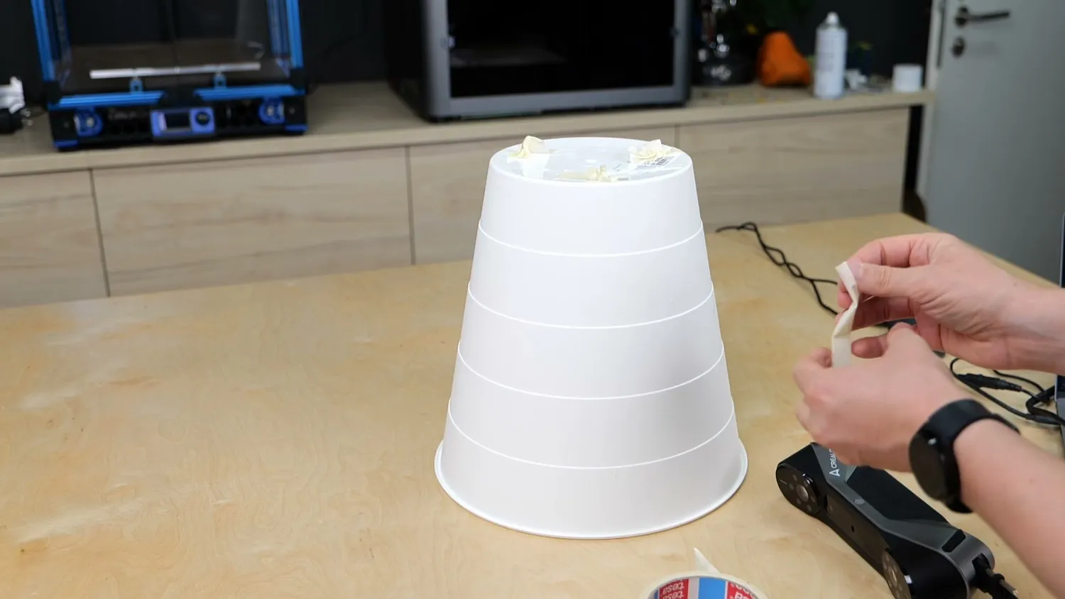 Crumbled-up painters tape gives the scanner features
On Creality’s Scanners, this will unfortunately also reveal one of the big problems, and this is software. Creality Scan has come a long way from where it was years ago and they very regularly release updates and add features. Yet one problem that annoyed me the most, which is very relevant for multi-orientation scans is that there is one major bug in their optimization algorithm. You might have already noticed some seam lines on some of the scans that I did, and this is not because the scans didn’t match. Creality Scan will always bend up the outer edges of every scan, even if you scan a perfectly flat or straight part. This is super systematic, can be found in every scan, and is in my opinion, one of the main reasons holding them back from a great user and scanning experience. I really have to call this out and hope that they fix this asap! You can get around this a little if you cut this edge away after you ran the optimization but on complex parts, this is hardly possible. The other option is post-processing the scan and using the smooth feature within Meshmixer or Blender, yet of course, that’s not the way if you want to do metrology.
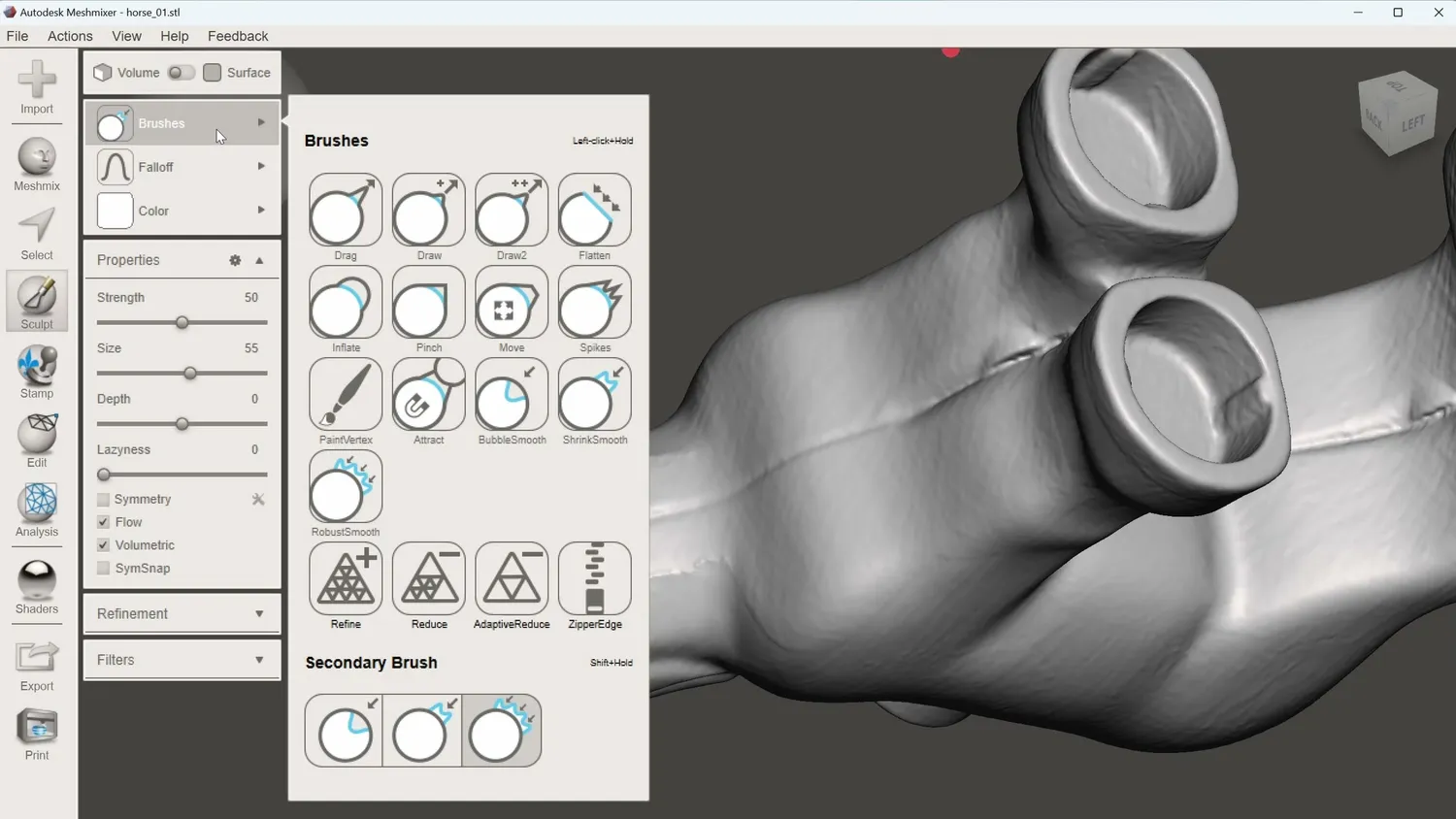 Smoothing the seam out in Meshmixer
Tip #9: Prepare your surface
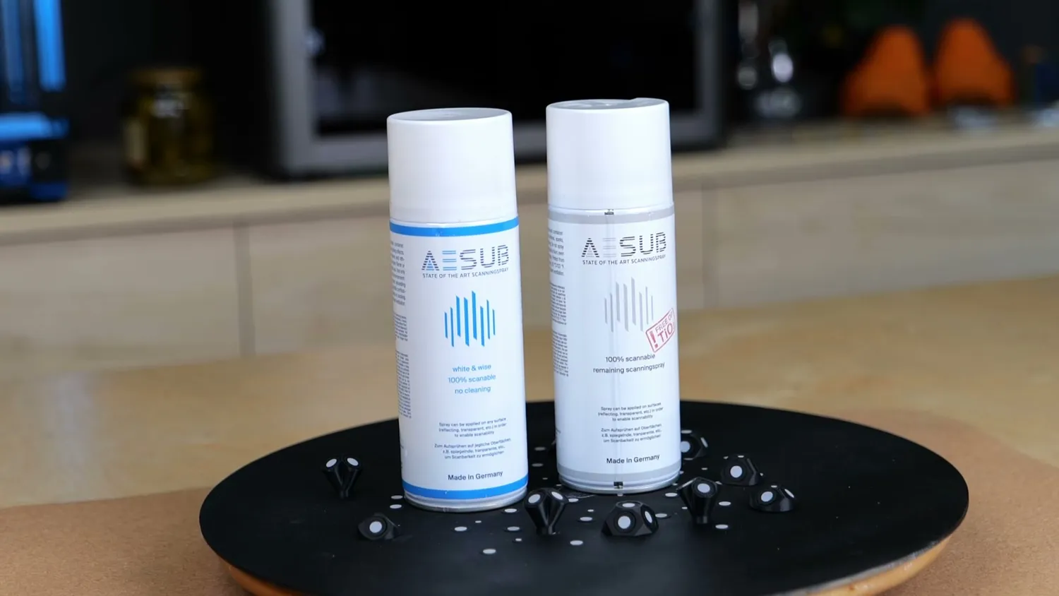
You might have noticed that one of the things I find most amazing about the Raptor in laser mode is that it can scan even shiny surfaces without any preparation. One of the chapters I wanted to put into here was surface preparation with scanning sprays but is that now obsolete? Yes and no. Yes, because you can scan most things without surface preparation, even this transparent container. But in most cases you will get even better results if you prepare your surfaces. Preparation means that you use these chalk or even self-cleaning sprays to remove shine and transparency from your part and get a bright and matte finish. Even the laser mode benefits from this and is able to produce even nicer scans if I spray them before scanning, both on shiny and transparent surfaces. And since the IR mode is even a bit pickier with surfaces you’ll often get better and more complete scans if you spray them a little. And better results also mean better accuracy for reverse engineering and metrology.
Tip #10: Measure your 3D scans
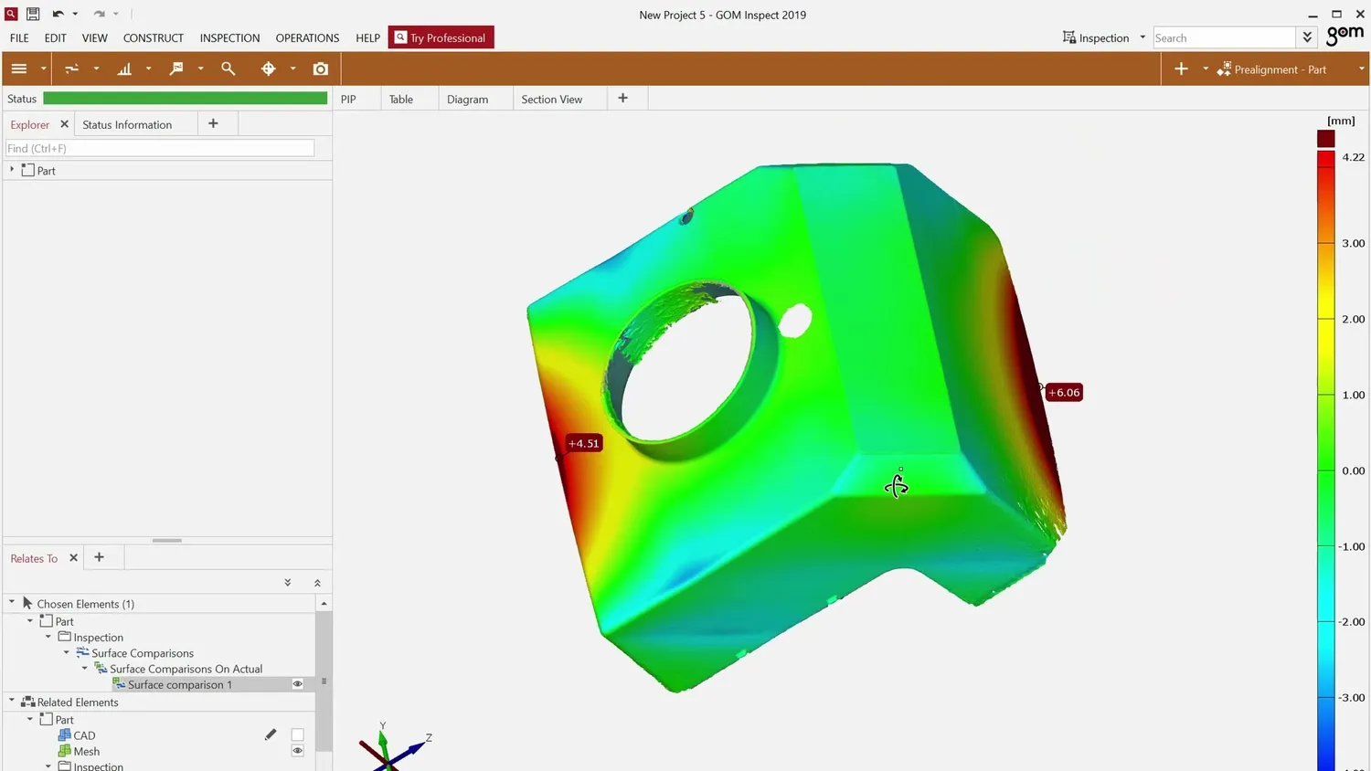
Speaking of metrology. After a good day the air intake cover for the AC finally finished printing and looked really good at first glance and also fit the AC perfectly. This shows why 3D scans as a reference can be so helpful to get a part first-time-right! Yet on closer inspection, I noticed that some edges of the unit were really warped. This is pretty common if you print thin-walled, big parts, because they lack stiffness to self-support. This is further amplified by printing this part in PETG and would even be worse in ABS for example. Estimating the amount of warping to make sure that this is still within your tolerances can be really hard manually yet this again is a great application of 3D scanning and something 3D scanning might be most often used for in industry. So I put the cover on my desk and started scanning it. Unfortunately I didn’t have a ton of success in geometry tracking mode so I added markers, which finally did the trick. Since the shroud has a somehow consistent wall thickness, I only scanned the outside, processed everything and then exported the STL. We already used GOM Inspect in the beginning where I told you how to get it for free. So I imported the scan as well as our ideal CAD geometry into the tool. Initially, they don’t match in their position, so we need to align them. Within GOM Inspect I used the best-fit alignment which was easily able to move the scan on top of the nominal geometry. We can then plot the difference between the two models which in this case shows a deformation at the two worst edges of over 6 mm, which is really significant. For our use case, this isn’t a problem, because it isn’t a critical feature but it could be a problem for other parts and now you know how you can check this yourself - if you have a 3D scanner. There are even ways to now pre-deform our nominal geometry in the opposite direction of this deformation to get an almost dimensionally perfect part after the print. If you’re interested in that, please let me know! The shroud by the way works perfectly well and finally keeps my studio at a temperature that’s comfortable for working.
If we are already within GOM Inspect I also wanted to show you another incredibly useful feature which is measuring dimensions within a scan. We briefly did this when we talked about the accuracy of 3D scanners, but you can do much more besides measuring the distance of two spheres. I won’t go into details, because GOM Inspect comes with a good tutorial, but generally, you can create fitting elements around features and then either measure these directly or use them to check angles or distances. ScanRuler does the same job in the browser if you don’t want to install anything. This can be tremendously useful for reverse engineering parts or getting measurements from features that are hard to measure conventionally.
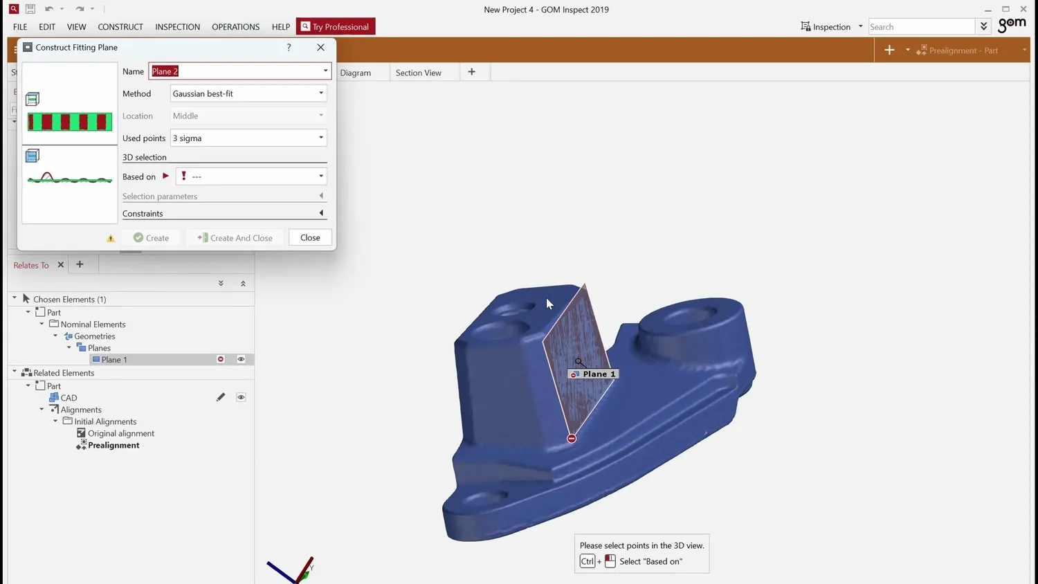 Fitting a plane to a scanned face
And there you have it! I hope I was able to show you useful applications and a ton of tips all around 3D scanning with common consumer grade scanners that have been becoming more and more popular these days. For my part, I love the new laser scanning mode of the Creality Raptor and started scanning everything - including a pickle but wish that Creality continues working on their software. Have you ever used a 3D scanner, and what is the top tip you can share?
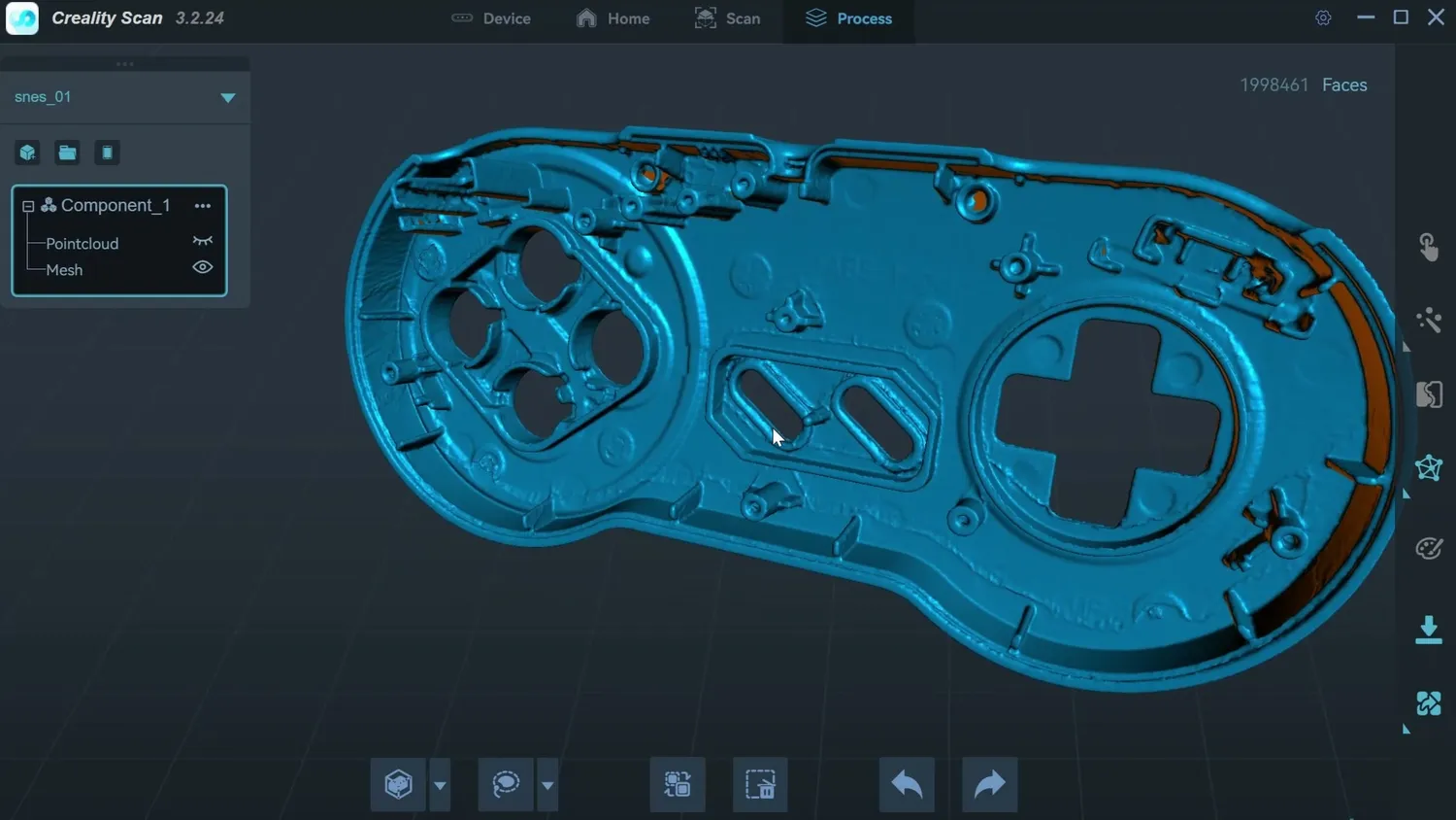 The SNES controller, scanned and merged
Links
Creality CR-Scan Raptor: https://geni.us/CR-ScanRaptor*
ScanRuler, my free browser tool for measuring scans: https://scanruler.com/
Payo’s channel, for more around 3D scanning: https://www.youtube.com/@Payo-TensileCreator
Why portable ACs suck: https://www.youtube.com/watch?v=_-mBeYC2KGc
All the scans I did for this article:
Pickle: https://www.printables.com/model/1007038-pickle-3d-scanned
AC cover: https://www.printables.com/model/1007921-aeg-axp26u338cw-chillflexpro-2-hose-conversion
OpenScan Benchy: https://www.printables.com/model/1007052-openscan-benchy-3d-scanned-with-creality-raptor
Garden gnome: https://www.printables.com/model/1007096-garden-gnome-3d-scanned-with-creality-cr-raptor
Vespa engine case: https://www.printables.com/model/1007903-vespa-engine-case-sample-3d-scan-with-creality-rap
Vespa front: https://www.printables.com/model/1007907-vespa-front-sample-3d-scan-with-creality-raptor
SNES Classic Mini controller: https://www.printables.com/model/1008341-snes-classic-mini-controller-sample-3d-scan-with-c
* Links marked with an asterisk are affiliate links — if you buy through them, I earn a small commission at no extra cost to you. As an Amazon Associate I earn from qualifying purchases. Thanks for supporting my work!