
Stop Printing Flat: The 45° Secret for Stronger Parts
Print orientation decides how strong a part is. Tensile tests at 0°, 30°, 45°, 60° and 90° show what angling really buys you, and where it backfires.
TL;DRthe short version
- Printed flat on the Prusa CORE One in 0.2 mm layers, my PLA coupons reached 63 MPa. The same samples printed standing failed at only half that, 31 MPa. Practically no filament print is equally strong in all directions.
- Layer adhesion is typically around 50% of the in-plane strength. It can go much higher with some materials, but also drop significantly if you print ABS with a lot of cooling.
- Angling really does help: the 45° coupons came in at 40 MPa, which is 27% more than the vertical reference. The 30° samples were a bit stronger at 44 MPa, the 60° ones weaker at 36 MPa.
- Strength doesn't change linearly between the best and worst angle but follows an S-shaped curve, so a slight tilt won't fix a layer adhesion problem. Aim for at least 45°.
- Printing on a corner needs a trick: rotate the part, cut a small section off with the slicer's cut tool for bed contact, add a brim. All my angled prints with supports failed because the part warped, released the support and the nozzle crashed into it.
- Angling fixes surfaces too. The Mount Fuji relief tilted 90° prints buttery smooth at 0.2 mm instead of stair-stepped, and a tilted 3DBenchy loses its bow line because the deck is printed gradually over many layers.
- My vacuum hose adapter printed at 45° gets roughly 30% more layer strength and moves the layers away from the stress concentrations. It did a great job through the whole studio renovation.
- But it's not always the magic bullet: my angled test hook held no more load than the standing one, and sometimes splitting a part and folding it, like the Multiboard system does, is the smarter answer.
How would you 3D print this part? This is a vacuum hose adapter for my belt sander that will be under constant strain during use. Would you lay it flat on the bed, just as it loads into the slicer or would you place it onto one of its ends but risking it breaking during use? I actually went with neither and chose something in between. But does that really help?
Here we’ll take a deep look at the crucial topic of print orientation: how it affects appearance, support material, and, most importantly, part strength, which I’ve tested with a bunch of tensile samples. So let’s find out more.
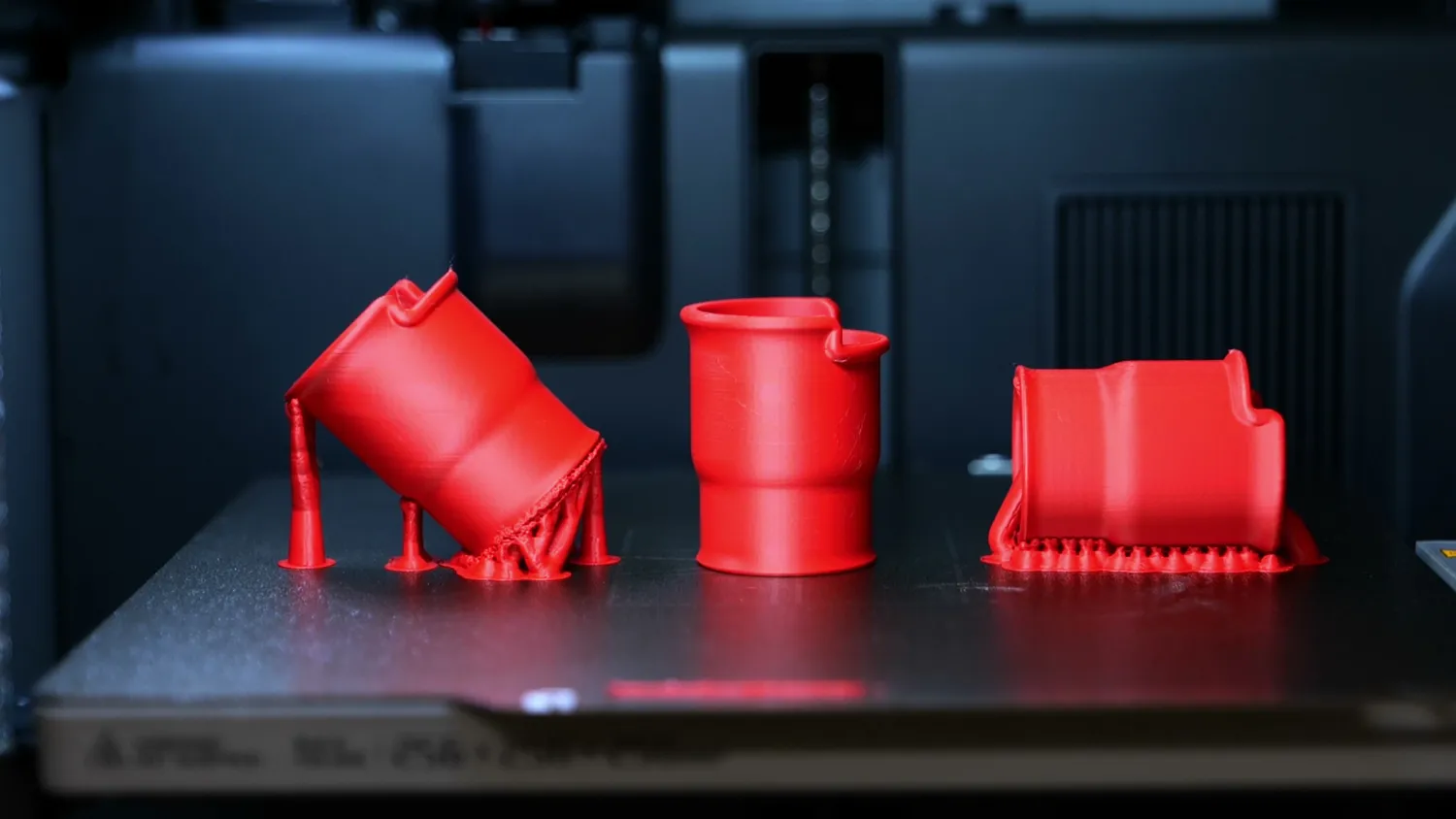
The same adapter in three orientations
Why we overlook print orientation
We often overlook the importance of choosing the correct orientation when printing a part. I admit I often do the same and rely on the auto orientation feature in today’s slicer, which optimizes the print for sufficient contact with the print bed and minimal support use. This improves printability but doesn’t necessarily find the orientation for the best strength! While many understand that layer adhesion is a common issue in 3D prints, few realize how much the performance of a part can vary depending on its orientation. Sometimes, the best orientation isn’t the most obvious choice.
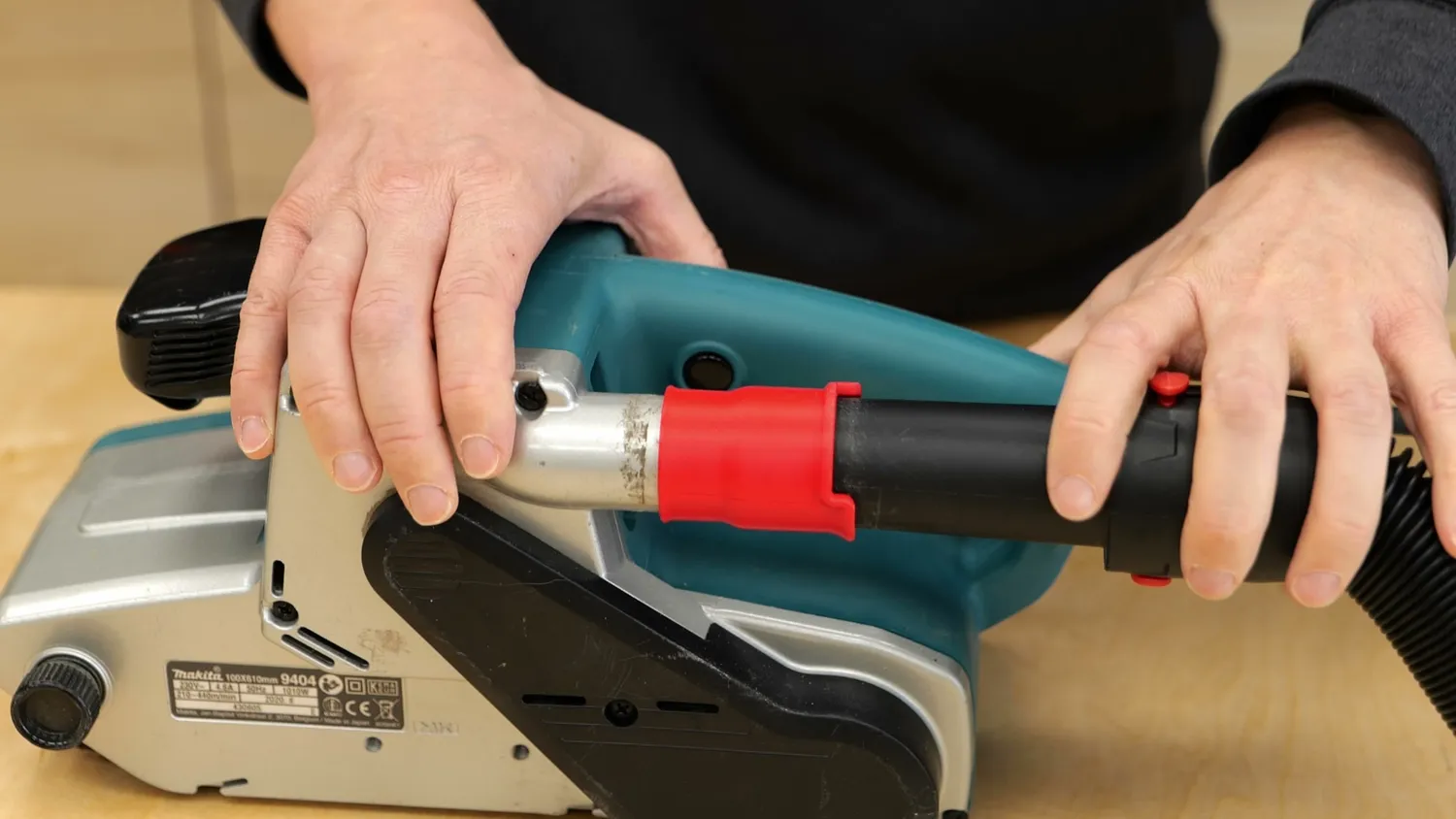
The adapter doing its job on the belt sander
Let’s begin with a simple bracket.
First of all, there’s an indefinite number of orientations you could print this part in. But the two orientations most of us would probably choose are on its side or on one of the larger flanges. Printing it on the big face is great for bed adhesion and reliability, but we face the problem that, at the point of highest stress, we have layer boundaries, right where the part will eventually break when it’s loaded.
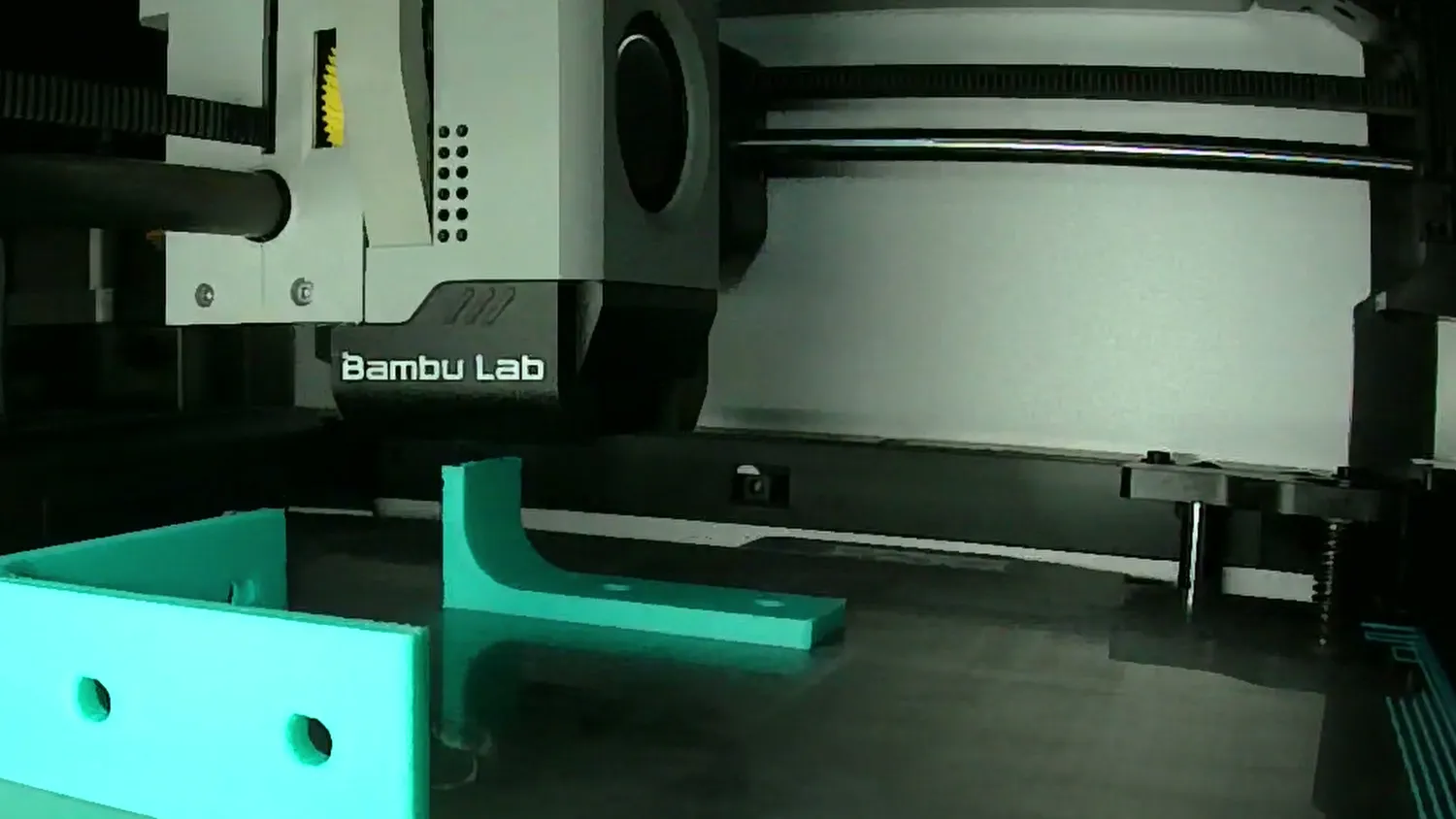
The bracket printed flat on its large flange
Anisotropy: 63 MPa flat, 31 MPa upright
One of the biggest challenges with filament-based 3D prints is their anisotropic strength. Anisotropic means that the properties of a material aren’t the same in every direction, and for FDM prints, that means they tend to break much easier if you pull the layers apart instead of along them. And the difference in strength can be significant. I printed a ton of samples for this article, especially to look at the strength of different print orientations, but let’s start with the basics and with parts printed at 0.2 mm layers on the Prusa* CORE One in Azurefilm Green PLA.
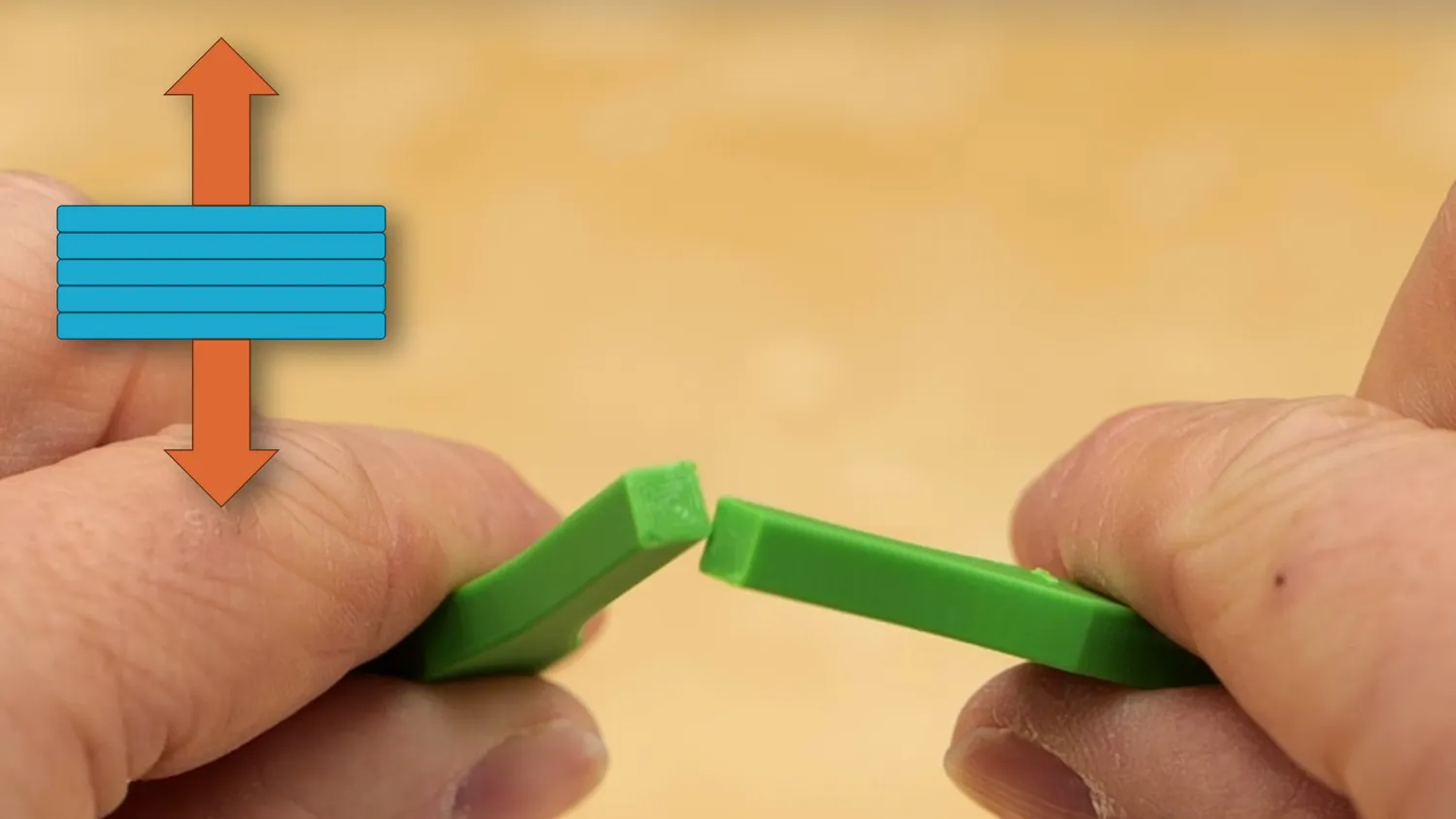
Layers pulled apart: the weakest direction
One set of samples was printed flat, whereas the other one was rotated 90° and printed upright. I then loaded them one after the other into my tensile tester and pulled them until they failed. The horizontal samples had an average strength of 63 MPa, whereas the ones printed standing failed at only half the load, 31 MPa. And this is very typical for 3D prints. Practically no filament print is equally strong in all directions. The newly deposited layer will only partially melt onto the one below, and the polymer chains are primarily oriented in the printing plane, causing additional weakness.
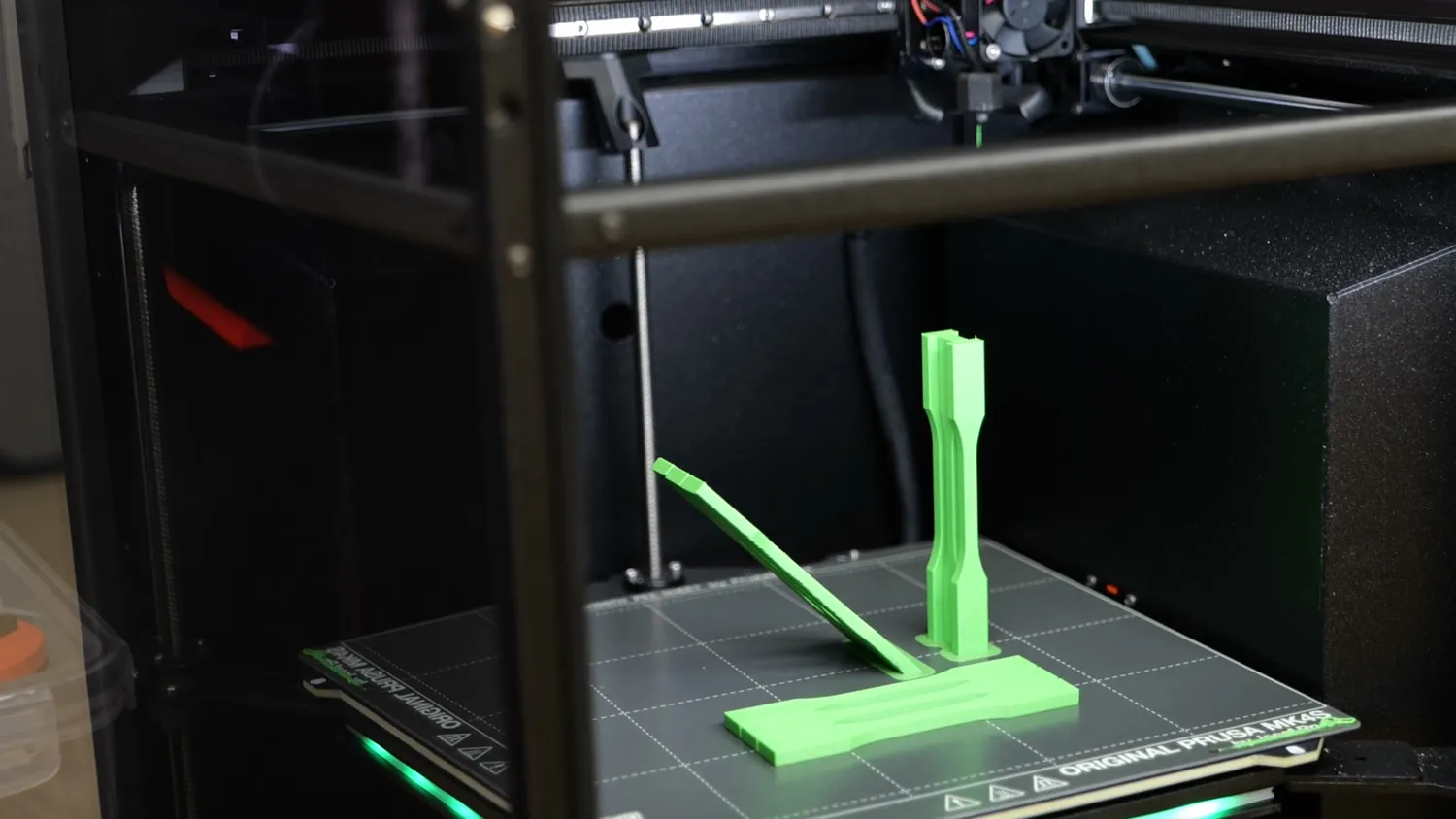
One set flat, one set standing
Depending on the material, printer, and settings you use, layer adhesion is typically around 50% of the in-plane strength, as we’ve just seen here. It can go much higher with some materials, but also drop significantly if you, for example, print ABS with a lot of cooling.
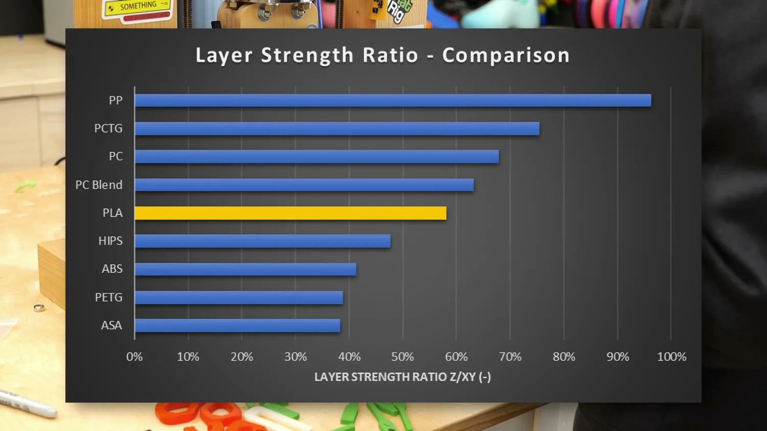
Layer strength ratio by material
Turning the bracket on its side
So, to increase the strength of our bracket without redesigning it, we simply place it on its side so that the stresses when loaded are more aligned with the print lines, where the part is strongest. But this can also lead to other problems with the bracket. Especially with warp-prone materials, printing on the side can cause the ends to lift and lead to print issues.
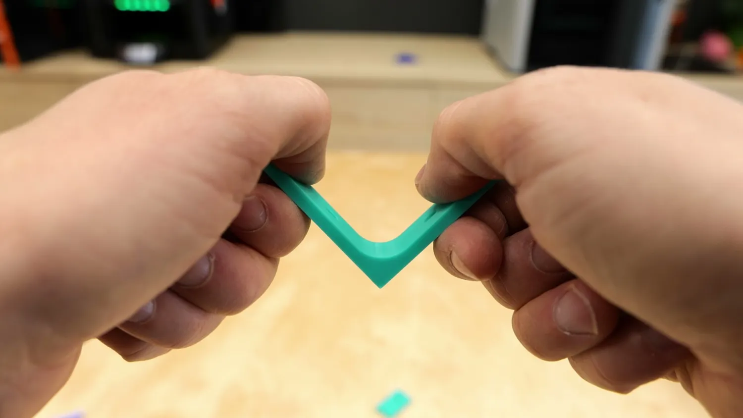
Loading the bracket by hand
And if we replace the standard through-holes with countersunk holes, we face another problem: when installing a regular wood screw into one of these holes, the tightening force will try to split the part. The layer lines again go directly through that hole, creating a weak point, which wouldn’t have been the case on at least one side of the bracket that was printed flat. So you see, even with such a simple part, the clearly strongest printing orientation has its own set of problems.
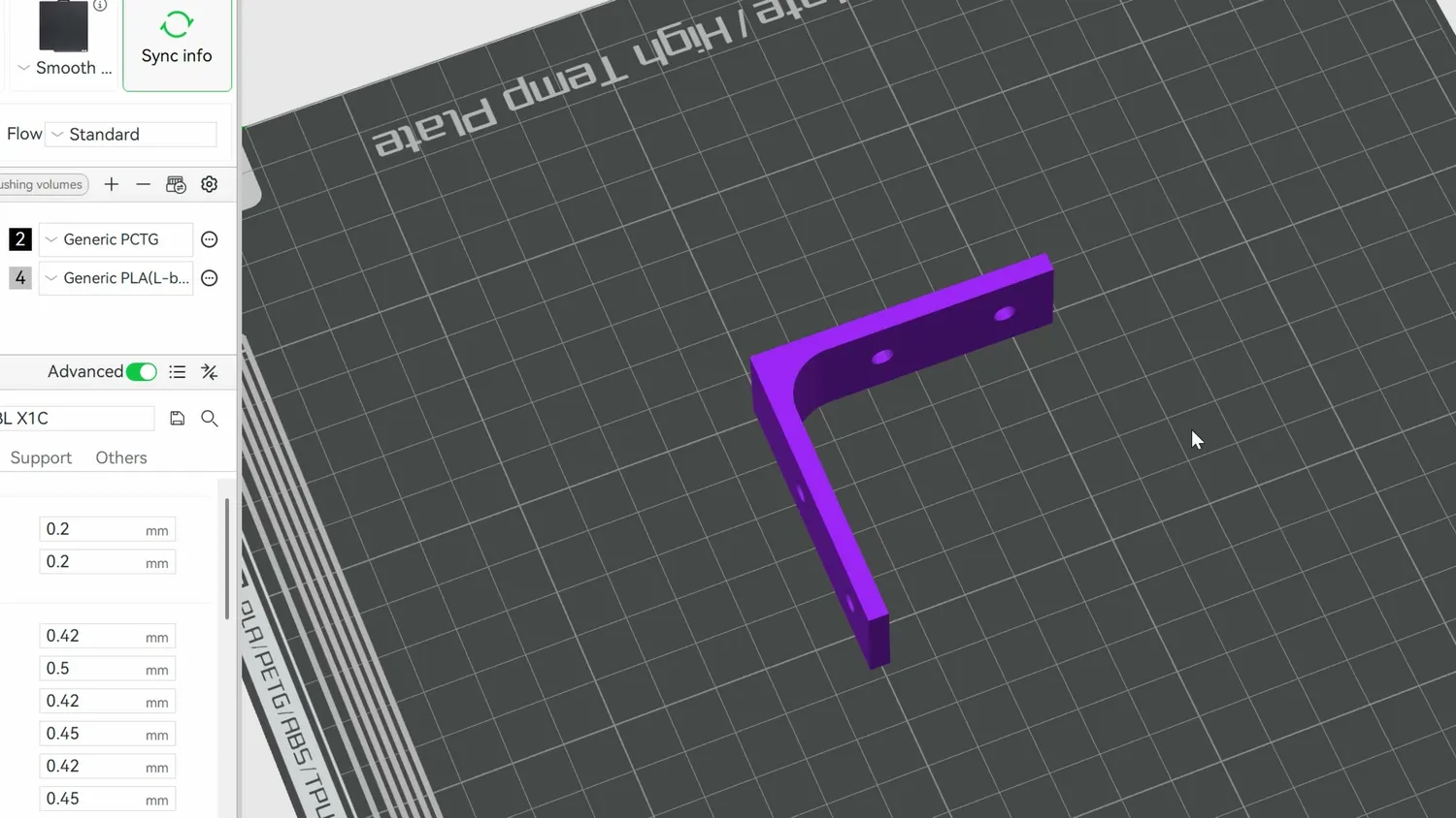
On its side the layers follow the load
The corner bracket has no ideal orientation
When we go one step further and look at a corner bracket, we quickly realize that there’s no ideal printing orientation anymore. Regardless of which side you place it on, there will always be one side pointing upward where the part is prone to premature failure due to weaker layers. In such cases, we either have to compromise strength in one direction or come up with another plan.
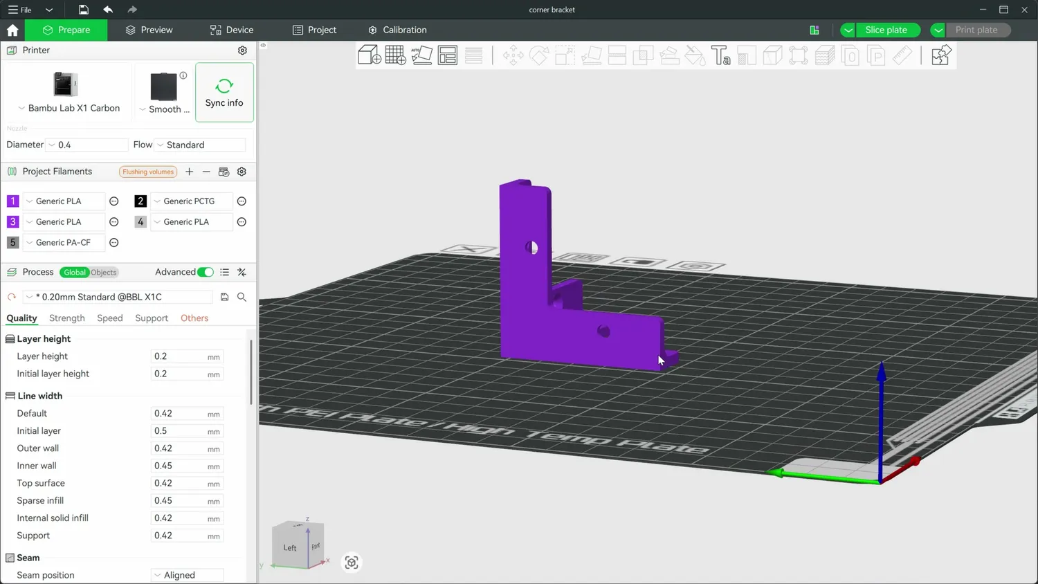
The corner bracket: no side is safe
So, if we have a part where, in a normal printing orientation, one side is very strong while the other is very weak, is there a way to improve the behavior or at least make the strength more balanced? I mean, if the strength of a 3D print is best when the load is along its layers and weakest perpendicular to them, maybe we can just angle it to get something in between. But does this really help?
Testing 30°, 45° and 60° print angles
Since I had the same question, I didn’t only print tensile samples horizontally and vertically; I also printed them at 30°, 45°, and 60° angles and put them to the test.
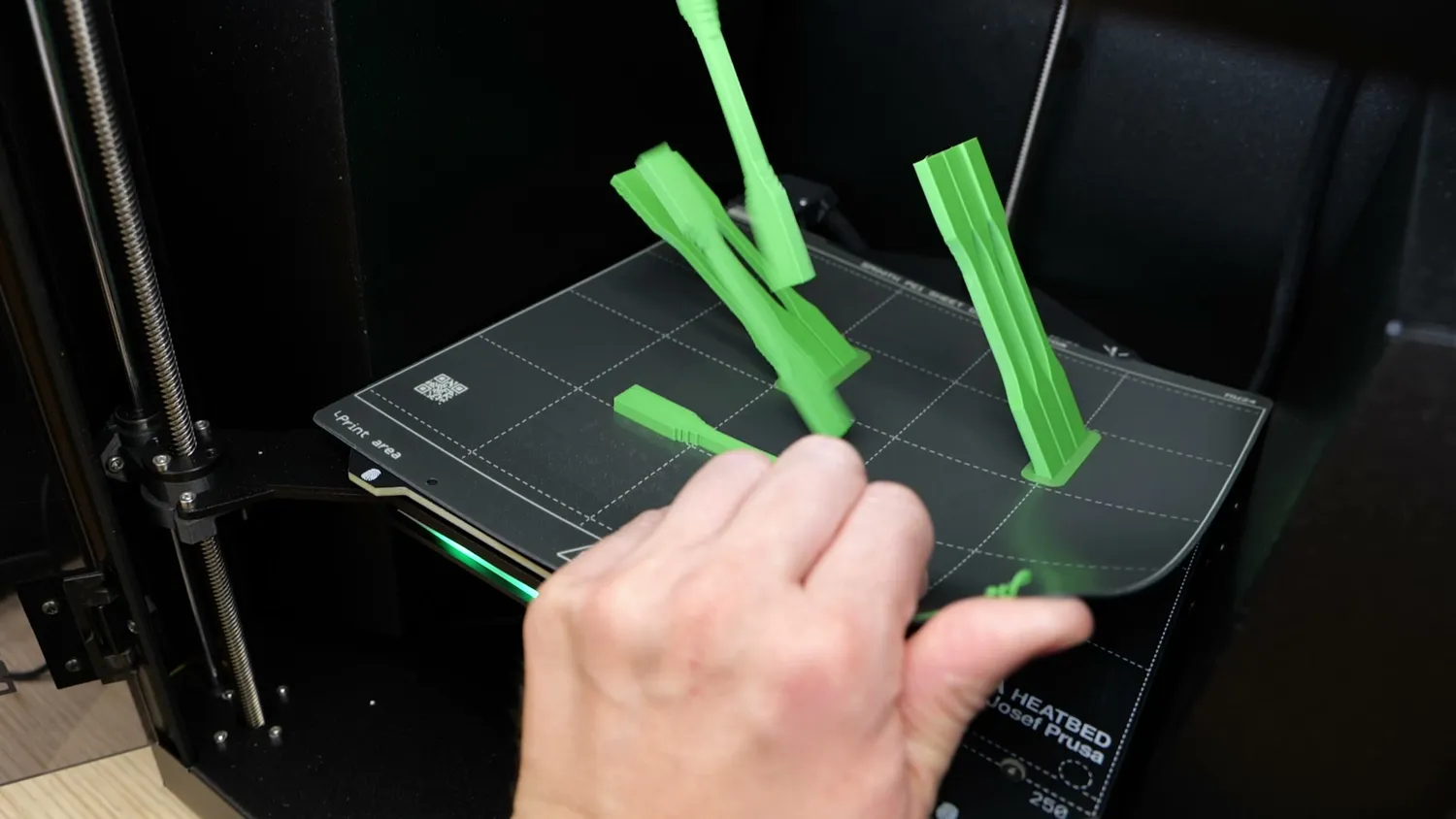
Coupons printed at 30, 45 and 60 degrees
The results were seriously interesting. The horizontal samples from before were at 63 MPa, and the vertical ones at 31 MPa. The three coupons printed at a 45° angle had a strength of 40 MPa. That’s still far from ideal, but angling the part improved strength by 27% compared to the vertical reference, which is significant. The 30° samples were even a bit stronger, failing at 44 MPa, whereas the 60° parts were weaker, at only 36 MPa on average.
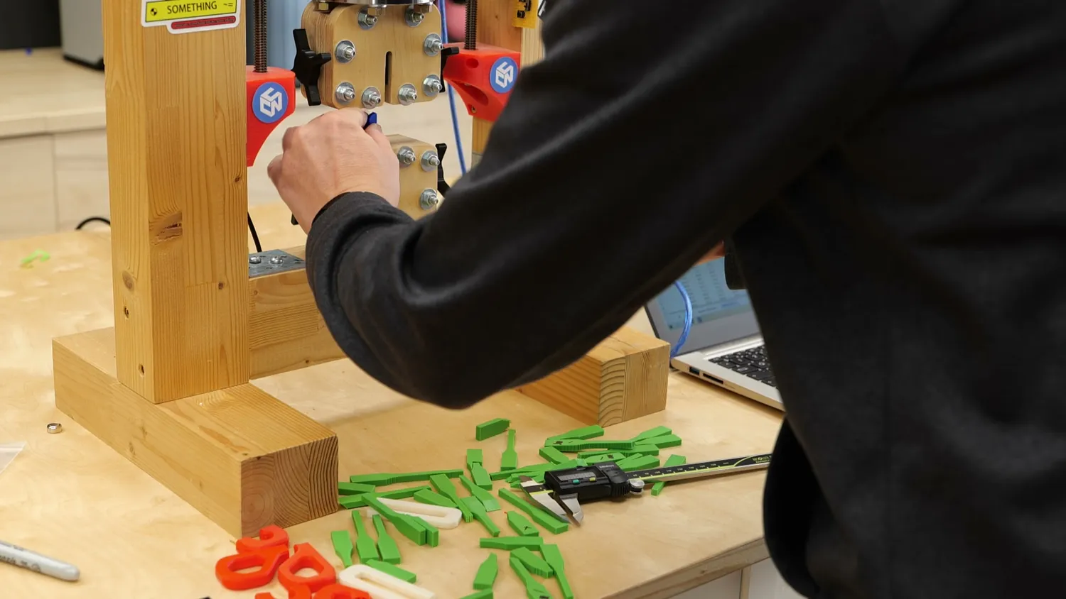
Every coupon went into the tensile tester
This aligns quite well with the analytical solution for orthotropic materials. The interesting thing here is that the strength doesn’t change linearly between the best and worst angles but follows an S-shaped curve. The reason for this behavior would be too deep for this article, but the takeaway is that small angle changes from the ideal orientation don’t do much, but past a certain point, the strength starts dropping fast. On the other hand, that means if you have a layer adhesion problem, angling the part only slightly won’t help much. You should aim for at least a 45° angle, which is a good compromise between printability and strength gain.
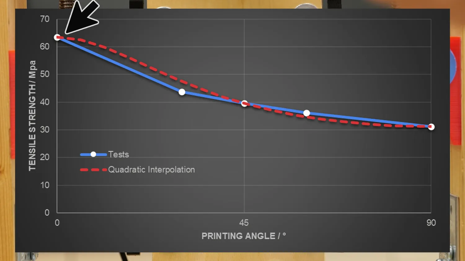
Strength over printing angle: an S-shaped curve
So, coming back to our corner bracket, printing it on its tip will improve the strength of the weakest member, while slightly reducing the strength of the others, but that’s still a good compromise.
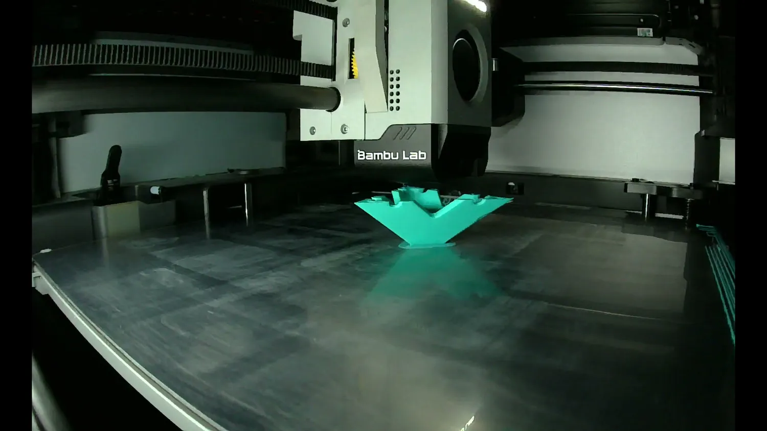
Printed on its tip, the compromise orientation
How to print a part on its corner
Printing a part at an angle isn’t always straightforward, though, because it often leads to minimal bed contact. In the case of the corner bracket, just a single point, which obviously won’t work. If I didn’t design the part myself, I often use a simple slicer trick: rotate the part into the desired orientation, then use the cut tool to remove a small section from a corner or edge, just enough to create stable bed contact. Add a brim, and with good adhesion, that often prints fine. But you can also add some manual supports for extra stability.
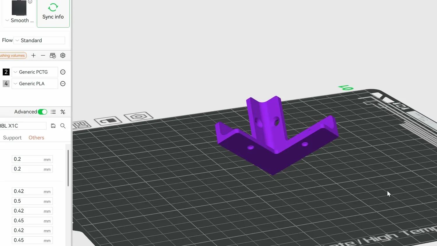
On its tip there is barely any bed contact
But you need to be careful here. I thought I was smart and did exactly that for my angled tensile samples, but all the prints with supports failed, while the ones without printed flawlessly. What happened was that even when printing PLA, parts always try to warp and curl up. Initially, the supports prevent this, but since part and support are only loosely connected (you want them to separate easily later), tension accumulates in the part until the support releases. Then the part springs up slightly, and the nozzle crashes into it, ruining the print.
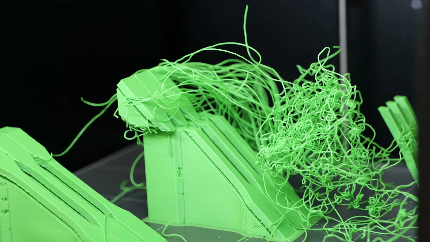
Every angled print with supports failed
You can get around this by designing custom supports that are only rigidly connected at a few points; I’ll link to a video about that from the Slant3D channel. The “dirty” way is to just decrease the Support/Object XY distance in the slicer and live with supports that are harder to remove, but hold the part firmly.
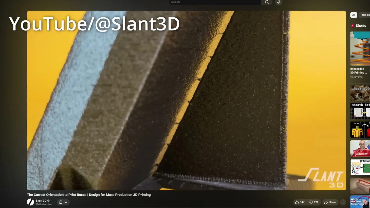
Custom supports explained (YouTube/@Slant3D)
Better surfaces and fewer shrink lines
Another often-overlooked benefit of printing a part at a different angle than you initially think is surface appearance. If you print a cube, the top, bottom, and side surfaces all look different. But printing the same part at an angle means all faces are printed with perimeters, and basically look and feel the same. I mean, sometimes that’s not what you want (many products are designed so that the bottom layer remains visible because it looks so clean), but especially for organic prints, this can be a game-changer.
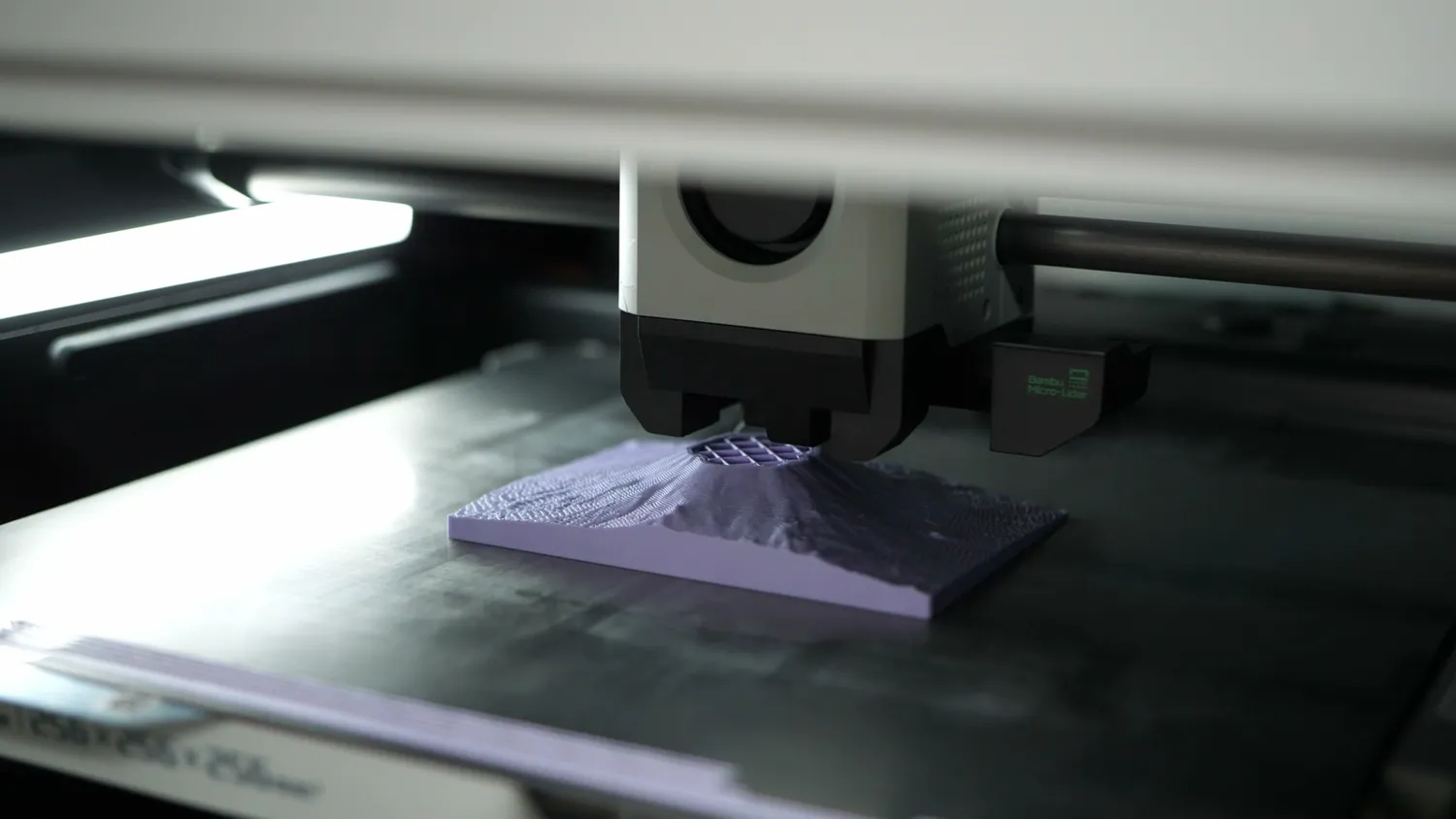
The relief as it loads into the slicer
Just look at this relief print of Mount Fuji. One version is printed as it loads into the slicer, the way also the author printed it, but that orientation leads to significant stair-stepping, especially on shallow slopes. If we tilt the part 90° on its side, it still prints great and produces a buttery smooth surface, even at 0.2 mm layer height. This has limits, of course: as long as the slope angles stay below roughly 45°, everything’s fine; anything much lower and the perimeters start printing into thin air or you’ll see exposed infill. But you’d be amazed at what a 3D printer can do with good cooling and good materials.
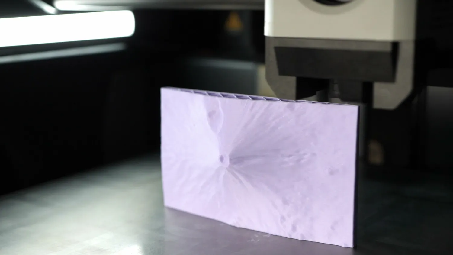
Tilted 90 degrees for a smooth surface
And this is not the only reason why the surface quality can benefit from angled printing. I’m sure you’ve seen notches on outer surfaces, the most famous being the 3DBenchy hull line, where a notch forms at the deck level. This is called a shrink line and happens when the thin hull is suddenly pulled together when the full deck starts being printed and the plastic shrinks when it cools down. A simpler example is this arch: at first, the two thin sides print independently until the roof connects them. The plastic contracts, the sides are pulled inward, and the next layer is printed offset, creating the visible notch. Printing this part at a slight angle not only improves the overhanging surface and almost eliminates the notch because only a small portion of the roof is printed in each layer, reducing deformation. So, if you print the 3DBenchy at an angle, the bow line basically disappears because the deck isn’t printed in one layer, but gradually over many.
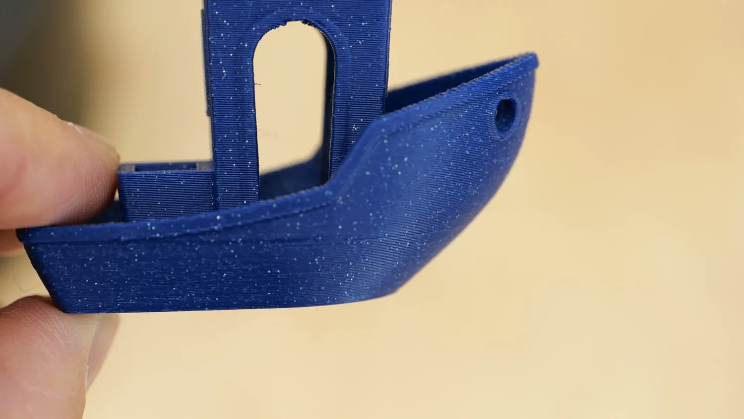
The famous 3DBenchy hull line
That doesn’t mean you should tilt your Benchy, but it’s important to understand why this happens and how angling can reduce shrink lines in FDM prints.
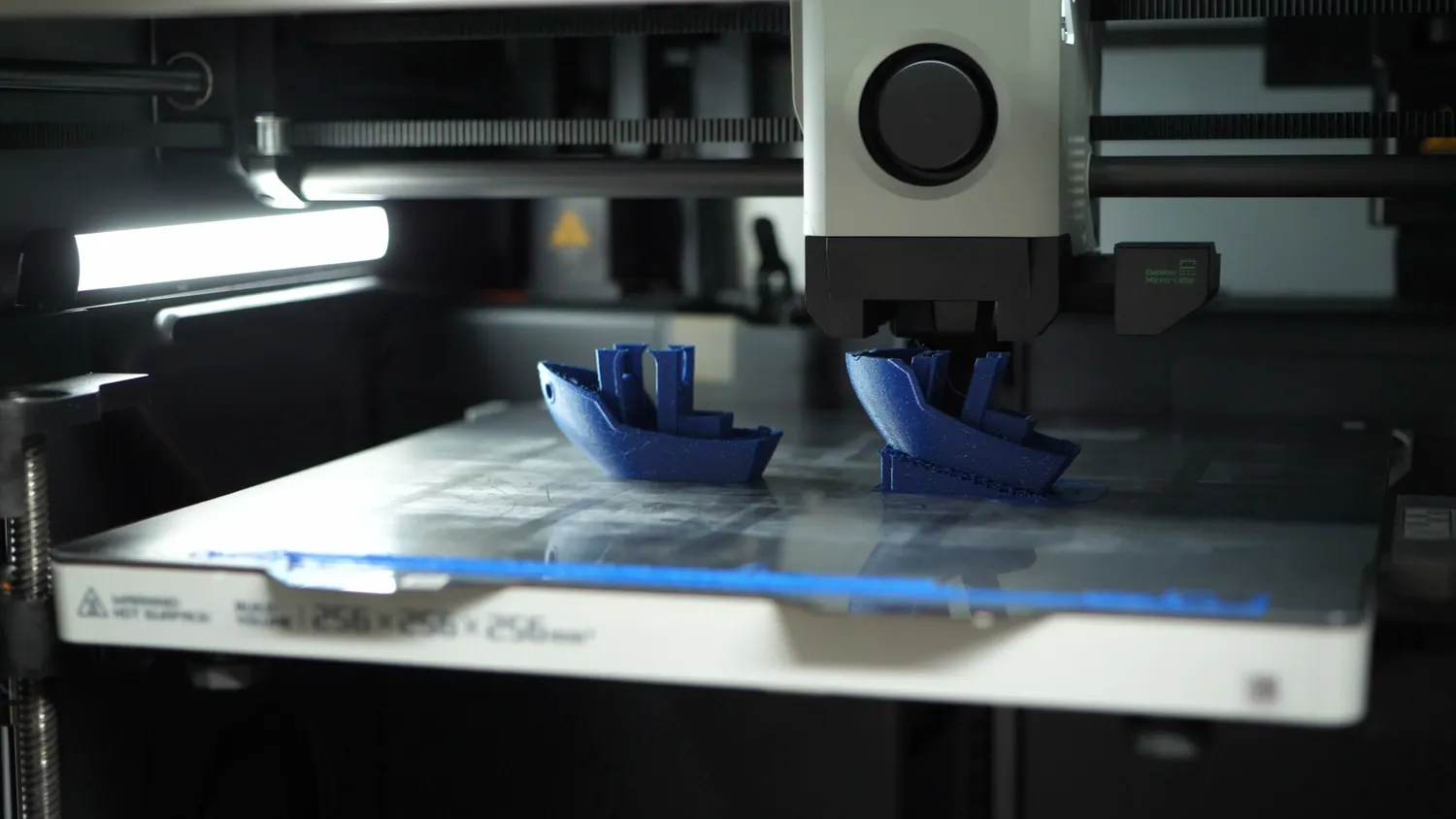
Benchies printed at an angle
Back to the vacuum hose adapter
With everything we’ve learned, let’s come back to the vacuum hose adapter for my belt sander. Especially for parts like this, thinking about print orientation and its effects on strength, surface quality, and necessary supports is essential.
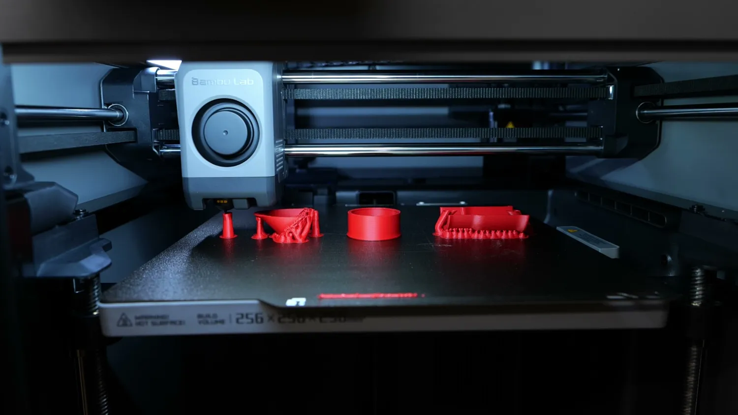
All three orientations side by side
Printing it flat is probably the worst choice: not only does it require the most supports, ruining dimensions and surface quality, but even though it’s now strong in one direction, it could split 90° to it. Printing it on one of its ends seems ideal because it doesn’t need supports, but now the layer boundaries are in the worst possible position, perpendicular to the load and right at the stress concentration from the sander and vacuum hose.
So I printed it at a 45° angle. Yes, that requires supports and a longer print time, but at this angle I’m not only getting roughly 30% more layer strength; the layers themselves are no longer aligned with the stress concentration points on the part. And printed like this, the adapter did a great job through the whole studio renovation last year.
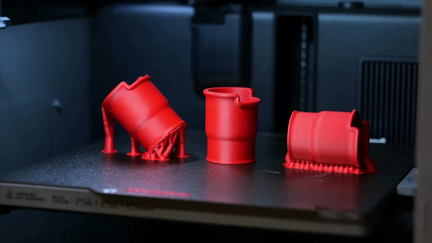
Flat, at 45 degrees and on its end
Think about orientation from the first sketch
Thinking about printing orientation can transform a design from merely “nice to look at” into something truly functional. And sometimes the most obvious orientation might not be the best! If you download a model from someone else, think about what you want to achieve and align your part accordingly, because the default position in the slicer isn’t always ideal.
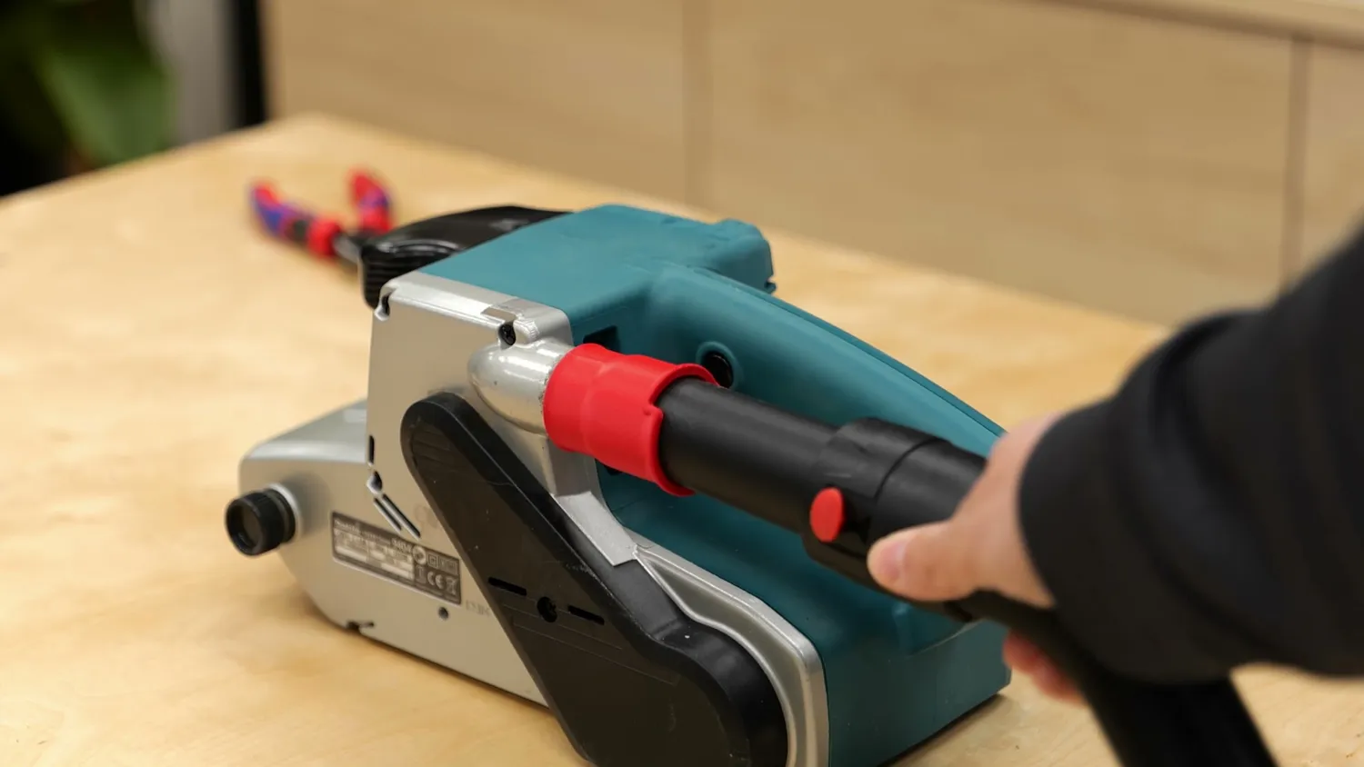
A model downloaded from someone else
If you design a part from scratch, start thinking about orientation as soon as you draw your first sketch, because it can literally make or break your part. How is the part loaded? Can you adapt the geometry to avoid supports? Which surfaces need to be precise or clean? And please - once you share your model, export the STL again in the proper orientation so others can print it as intended - because that’s not always obvious and can lead to frustration!
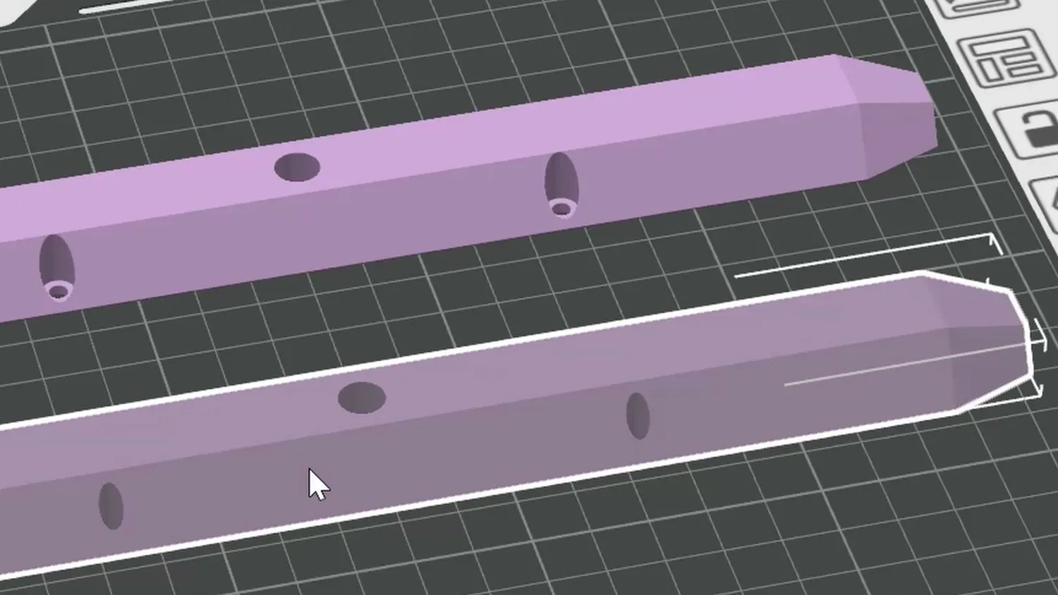
Orient the part before you export the STL
Angling isn’t always the magic bullet
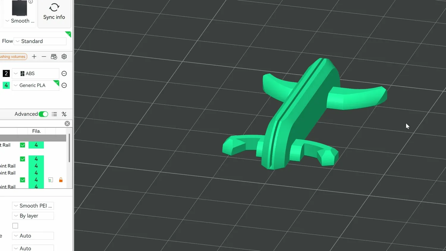
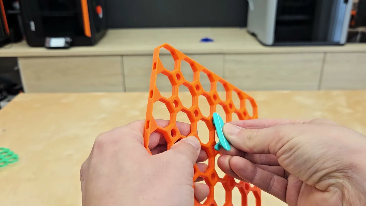
But I also want to be completely transparent here. Sometimes, changing the orientation can make things worse, and this already starts with the quality of the corner bracket, where at this angle, the overhangs can curl up a little. You can also shift problems. Initially, my vacuum hose adapter always broke during use, but when I first printed it at an angle, it split at 45° during installation because it was too tight. After re-printing it with the right dimensions, it became super durable! Similarly, my test hook printed at an angle did not hold more load than the one printed standing, and the point of failure just changed, because the loading itself is complex. The interaction with infill, perimeters, and top and bottom layers can cause issues. Angling can help, but it’s not always the magic bullet. So sometimes, you need to think a bit outside the box, and this is where I need to highlight some parts of the Multiboard organization system. This part clips into a baseboard to hold a bin, and at the obvious printing orientation, the hooks are weak. Printing it at 45 or 90° would likely improve strength but would require supports. Instead, they split the part in the middle and connect the halves with a thin bridge. When you finish printing, you fold it, resulting in a super-strong and efficiently printed part. And there are plenty of parts where they do this and it’s really worth looking into. Kudos on that!
3D prints can be complex, and for most parts, there’s no single best printing orientation, only compromises between strength, quality, accuracy, and supports. And these factors often compete with each other. But if you keep just some of these findings in mind, your prints will not only look better but also perform better!
But what are your thoughts on this topic? How often do you change the orientation of a part to make it print better? And what’s your best example of making a stronger or cleaner part just by reorienting it?
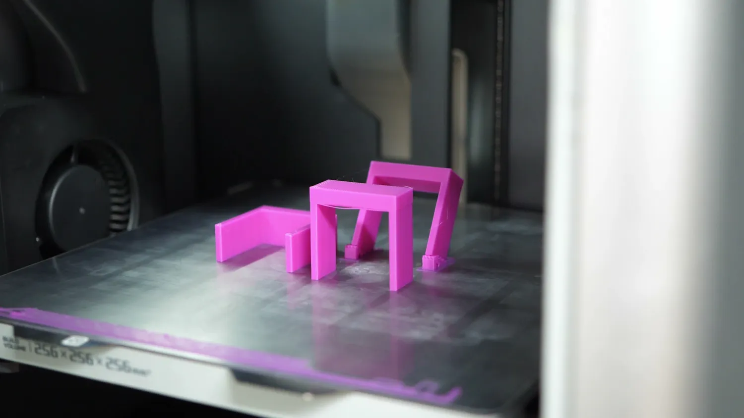
A few of the test parts
* Links marked with an asterisk are affiliate links — if you buy through them, I earn a small commission at no extra cost to you. As an Amazon Associate I earn from qualifying purchases. Thanks for supporting my work!