
Machining a 3D printer nozzle on a Mini Lathe
I finally bought a mini lathe, so the first real project was turning a 3D printer nozzle from scratch. Then I cut it open to see how bad the inside really was.
TL;DRthe short version
- A Sieg SC2 mini lathe, 500 W with 400 mm between centres, about 1000 € delivered plus another 500 in tooling. I stripped it, cleaned the ways and adjusted the gib strips; the one real addition is a Multifix tool post, which is worth every penny.
- A nozzle makes a great first project because it packs a lot of awkward features into a tiny part, above all the 0.4 mm hole in the tip.
- I used the older E3D V6 drawing without the 60° internal taper, since I have no tool for that. The stepped bore isn't ideal for flow but probably still gives 95% of the performance.
- MS58 brass in 7 mm hex stock, so the flats come for free. Two setups: threads and internal bores first, then turn it around for the tip and the orifice.
- The 7.5 mm length is the reference dimension between the two setups. Get it wrong and the small bore ends up the wrong length, hurting the flow.
- Threads either with a die in a tailstock holder, which takes seconds, or single-point with a threading tool at 1 mm feed per revolution. Tedious, but oddly satisfying. I used a nut as the gauge.
- For depth I made a makeshift DRO, clamping a printed part to the quill as a stop for a dial gauge, and cleared chips often so the bore didn't need reaming afterwards.
- Cut open on the CNC router, the internal finish is better than plenty of nozzles I've seen, though the bores came out slightly shallow so the orifice is a bit long. Printed side by side against a genuine E3D on my toolchanger, I couldn't see a difference beyond the colour.
Well, it finally happened, and I bought myself a Mini Lathe after desiring one for years. You ask why? Well, that’s also what my wife asked. As This Old Tony once said, you always need one more milling machine, and I think that also applies to lathes. Well, I regularly have projects in mind like for example special nozzles for the Filastruder that would require such a tool. I desired having a lathe at my disposal because this is, in my opinion, one of the most honest ways to machine metal. It’s such a pleasure to dive your tool into the material, adjust the pressure with your hand and just feel the metal being peeled off. Probably also one of the reasons why I’m currently not planning to convert it to CNC, or what do you think? I don’t have a lot of space and it had to go down into my basement, so a Mini Lathe, in my case the Sieg SC2 with a 500W motor and 400mm distance between the centers, was the machine of choice.
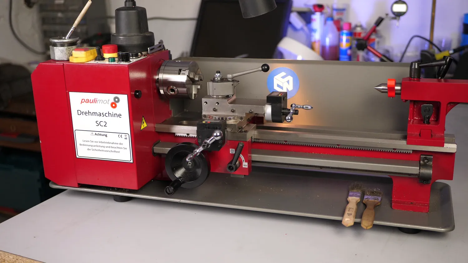
Paulimot Sieg SC2
The lathe
I bought mine from a local vendor that also just imports them but I hoped for more quality control on their side. The lathe was around 1000€ delivered plus another 500€ for additional tools and accessories. You can get similar models cheaper, but this one at least came with all metal gears and a tailstock with a quick lock. Even though I didn’t do any real modifications, I still took it apart, cleaned all the ways put it back together and adjusted the gib strips. The only thing I really changed is adding a Multifix Tool Post, and that thing is a piece of beauty and worth every penny!
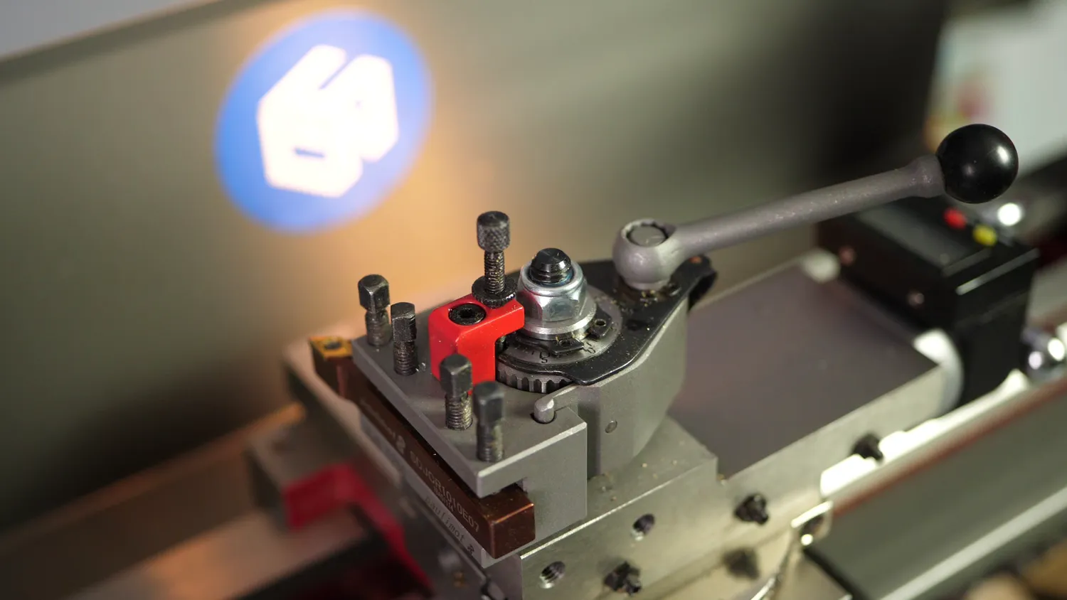
Multifix Toolpost
Why machine a nozzle
So I had it for a good two weeks and seriously enjoy using it. I’m not a trained machinist and the last time I was working on a lathe was 13 years ago. To learn using one of those machines again, I thought it might be interesting to try to machine a 3D printer nozzle, because it has a lot of features that are a bit challenging and a good way to learn, most notably the 0.4mm hole in the front! I’ll be using the E3D V6 nozzle design but chose an older version of the drawing that doesn’t have the 60° taper on the inside because I don’t have a tool for it. I’d be interested to know from experienced machinists if that could be done by just grinding a drill bit to that tip angle. The older design uses a stepped bore which is not perfect for the flow, but will probably still give us 95% of the performance. I did a quick design from the original in Fusion 360 to create another drawing that had all the dimensions that were interesting for me and also important for machining, especially the depth of the bores measured to the tip of the drill bit.
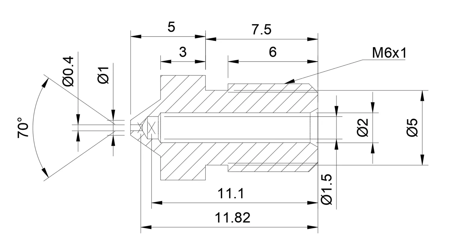
E3D V6 nozzle drawing with machining dimensions and stepped bore
All right, so let’s get to the lathe! I’m using brass for the nozzle and to be more precise MS58 or a brass with 39% Zink and 3% Lead, which is probably the most common brass alloy and well suitable for this application due to its good thermal conductivity and machinability. Since I was lazy and wanted to save myself the step of later milling the flats, I directly purchased 7mm hex stock. Since it wasn’t that long, I didn’t bother cutting off a bit and directly put it into a 3-jaw chuck. I figured that I would need two setups for machining the nozzle. We’ll make the M6 thread and the inner bores in the first one and then turn everything around, and machine the tip, as well as the tiny nozzle bore.
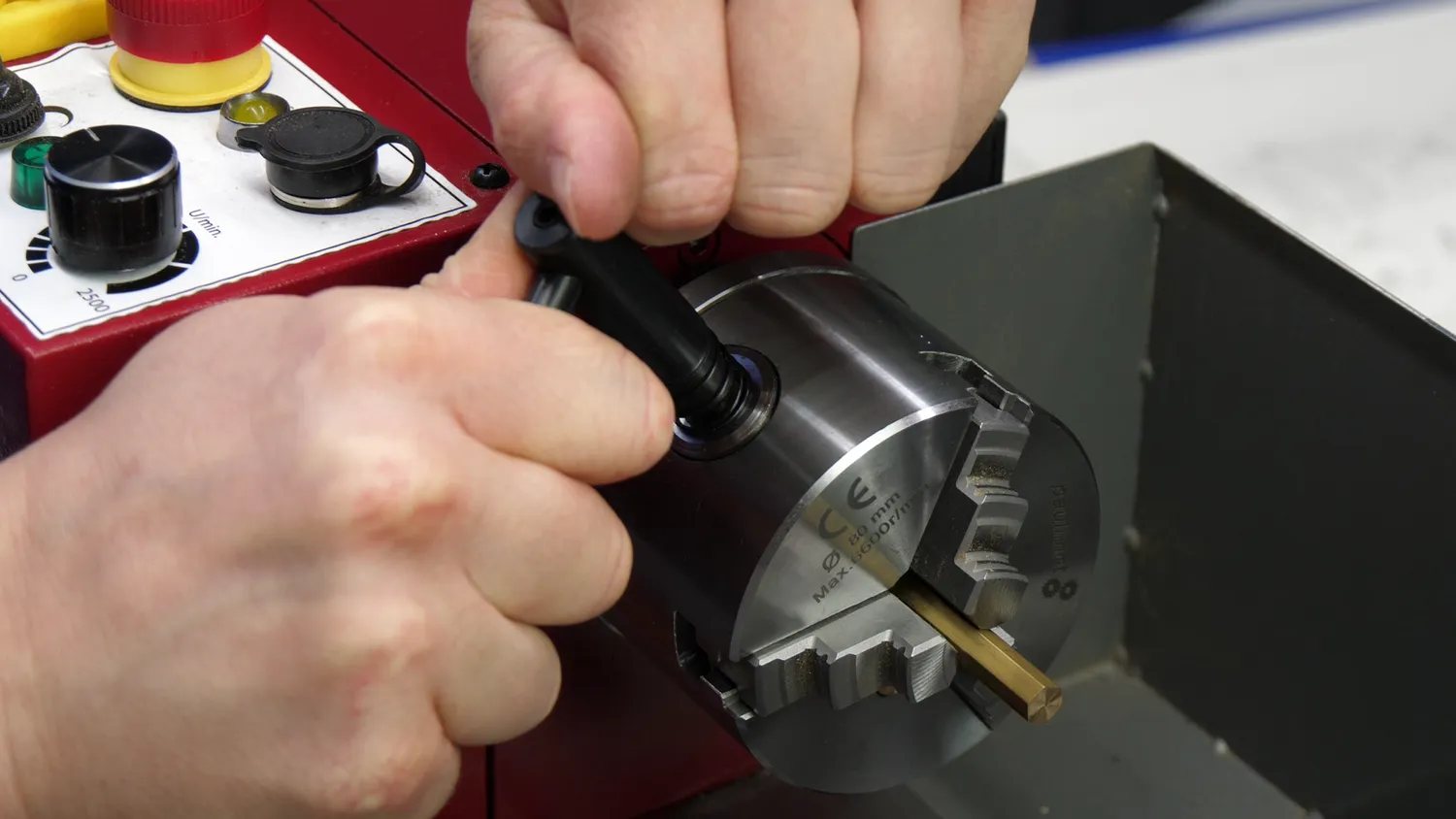
Hex Stock in the 3-Yaw-Chuck
For the first operation, I’ll be using a 1.5mm wide, high-speed steel, parting tool to create the thread relief. I locked the carriage into place with the half nut lever while the feed rod was disengaged. I first faced the stock off to have a reference surface and zeroed the digital handwheel dial. Then I moved the tool the 7.5mm mark machined away the hex, zeroed the crossfeed handwheel dial, measured, machined away more, and checked the final dimension. With this high-speed steel parting tool, I have to go quite low in terms of RPM to get a good cutting result. The 7.5mm need to be pretty precise because they form the reference dimension for the second setup and if they are off, the length of our small 0.4mm bore might be off, causing non-optimal flow.
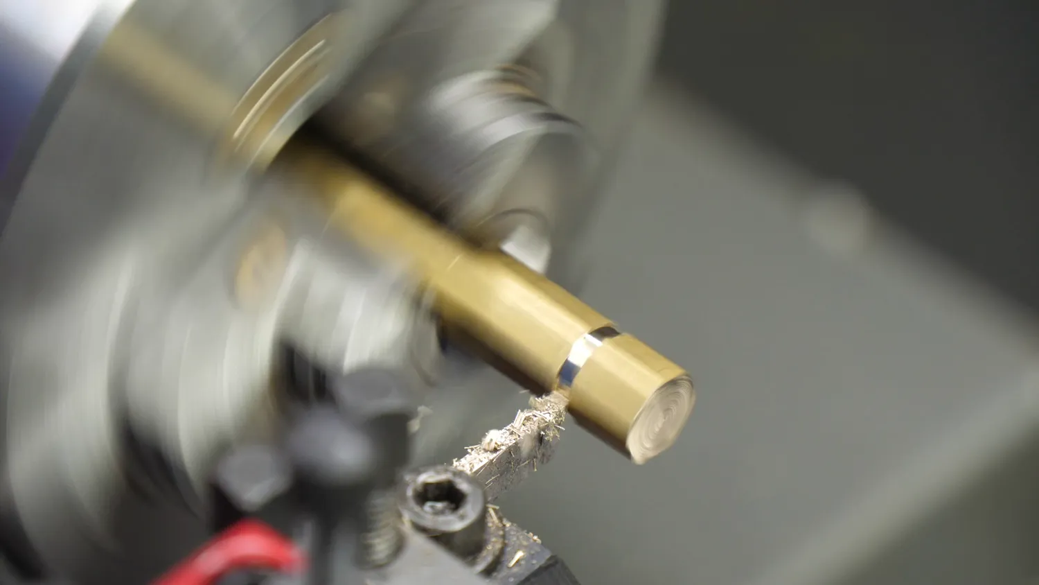
HSS parting tool
Next, we need to get the threaded section to size, and for that, I used a regular left-handed cutting tool with a carbide insert. Many claim that the Mini Lathe is not made for carbide tooling because carbide needs high cutting speeds and a stiff machine, but so far, it worked pretty well for me and didn’t require me to learn to grind my own tools from high-speed steel. I turned down the hex so that I was able to measure the part and then removed the rest of the material. I slightly de-burred the edge of the relief with this tool as well.
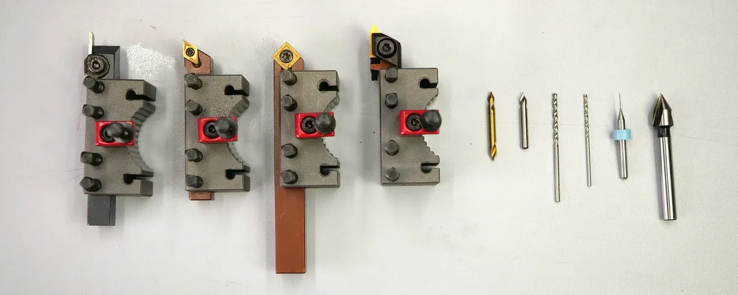
The 10 Tools used to machine the nozzle
Next, we use a square insert for machining the chamfers. I slightly touched the edge for zeroing and then machined a nice, big chamfer. I also added a small chamfer at the hex just for visuals.
Cutting the M6 thread
For the threads, we have two options. The first and easy one that works with these small threads is using a regular thread cutting die and a tailstock die holder. This contraption provides you with an easy way to align the die with the workpiece. The holder is rotatable and free to move on its axis. You start the lathe at low RPM , hold the die in your hand until you reach the end of the thread, and then just let it go. Perfect threads in a matter of seconds.
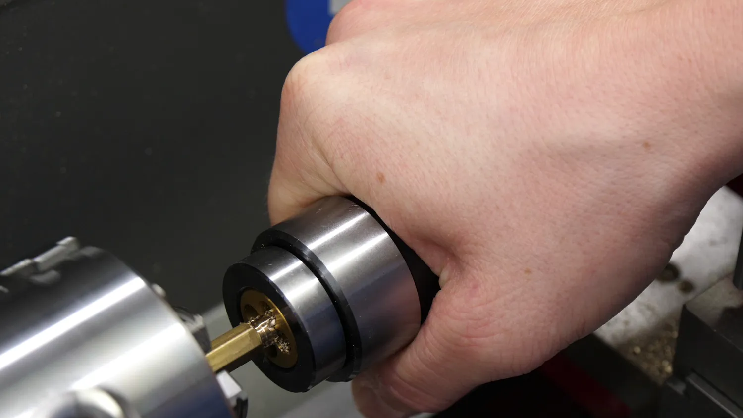
Thread Cutting with a Tailstock Die Holder
The more advanced, versatile, and in my opinion, also most satisfying way is to use a threading tool. Here, you lock the rotation of the chuck to the movement of the carriage by gears in the back that connect to the feed rod. By selecting the specific combination of gears, this results in 1mm of feed per rotation of the spindle, just as we need it for our M6 thread. So we engage the half-nut, slowly cut one pass, retract the tool a little and move it back in reverse. The first pass is a scratch pass on which I check the pitch with a pitch gauge, to make sure that I selected the right combination of gears. Cutting threads this way might be a tedious process, but I find it oddly satisfying. The deeper we get in the thread the more material the tool cuts. I only took shallow passes and used a spring pass from time to time and plenty of cutting oil. You could check the thread with special tools, but since I don’t have those and precision, in this case, isn’t crucial, I just use a nut as a gauge and go deeper and deeper until I could screw it on.
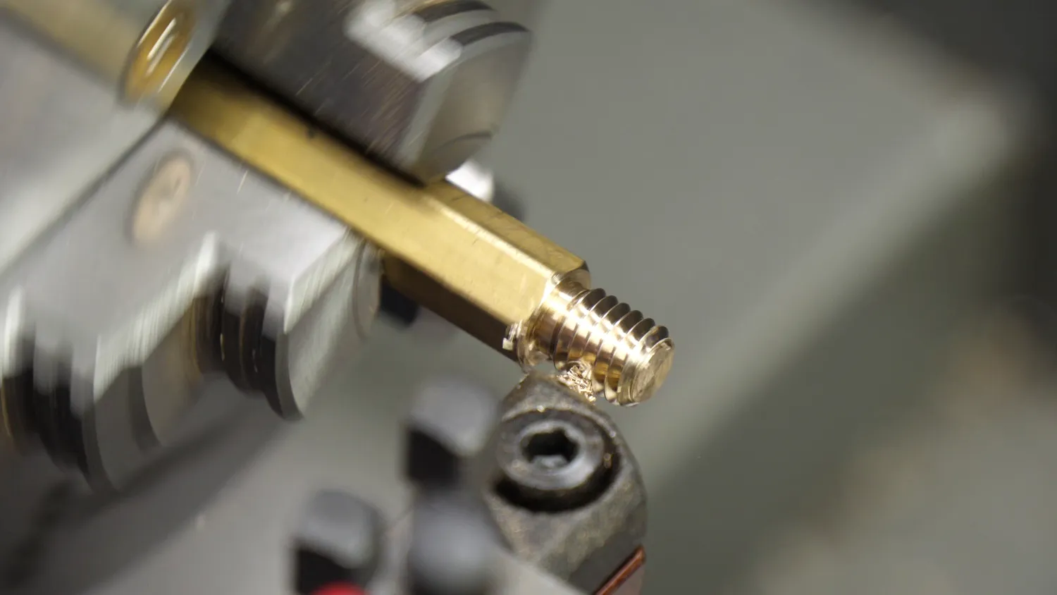
Thread Cutting Tool
Drilling the deep holes
The last operation of this first setup is drilling the deep holes. For this I put a drill chuck in the tailstock and started with a center drill, that is rigid and doesn’t wobble around and will create a pilot hole for the longer and more flexible drill bits. So the stepped hole needs to be reasonably precise. The tailstock has a scale on it, but that’s more for rough depth estimation. I didn’t know any better and made myself a makeshift DRO, by clamping a small, 3D printed part to the quill and using that as a stop for a dial gauge.
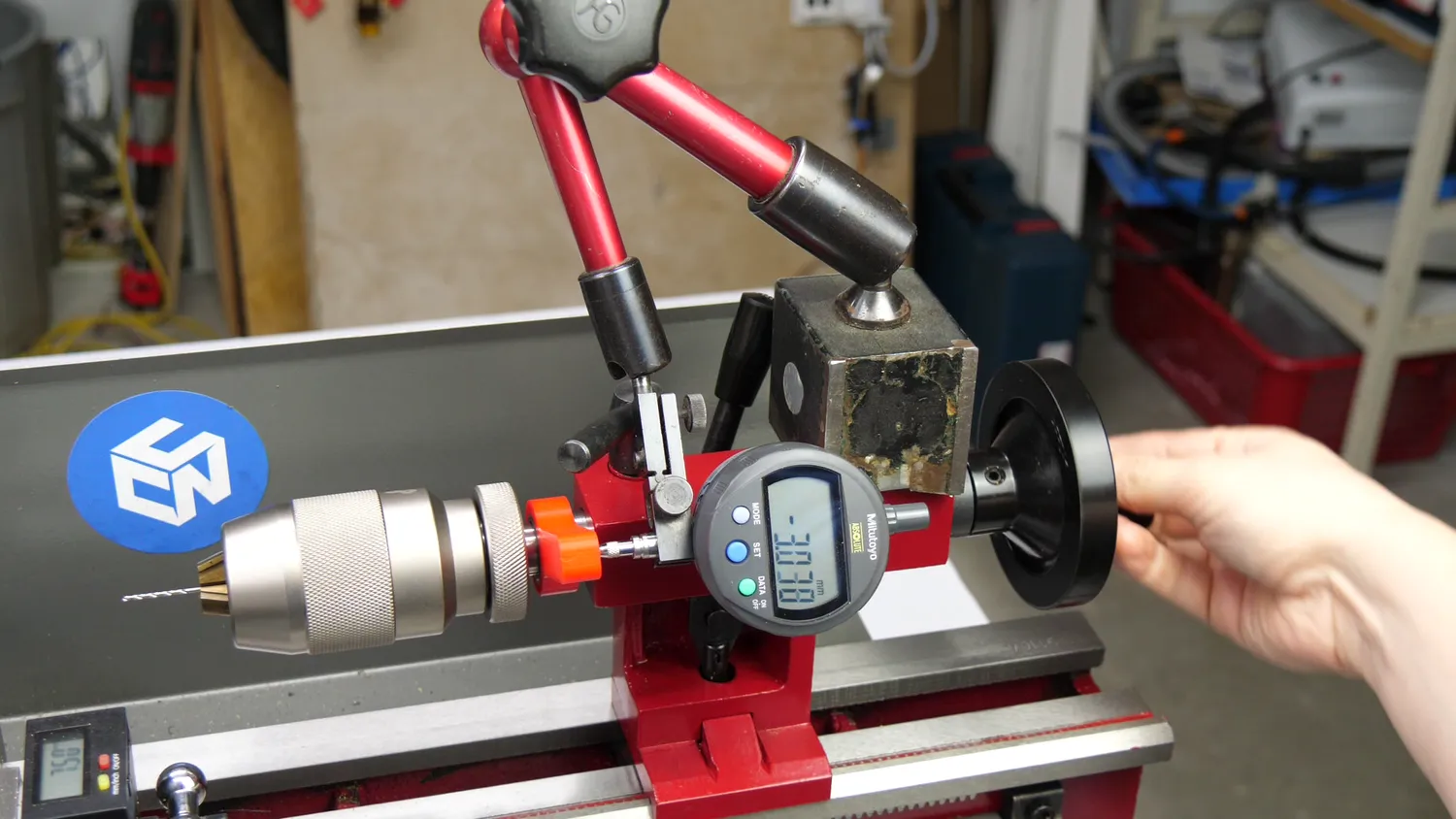
Makeshift DRO
To find the zero-depth, I used a thickness gauge between the drill bit and the part to measure where I was. First, I drilled the 1.5mm hole and regularly retracted the bit to clear it from the chips. The 2mm hole was way easier to machine because the amount of material that is removed was quite low. Since this operation is crucial for the interior surface finish, I still cleared the chips regularly because I wanted them to rub against the surface as little as possible, and I think this way, you don’t even need to ream the bore. In the end, I just added a small 60° chamfer with a chamfer bit, before I parted the nozzle blank off with around 2/10 of a mm extra in length.
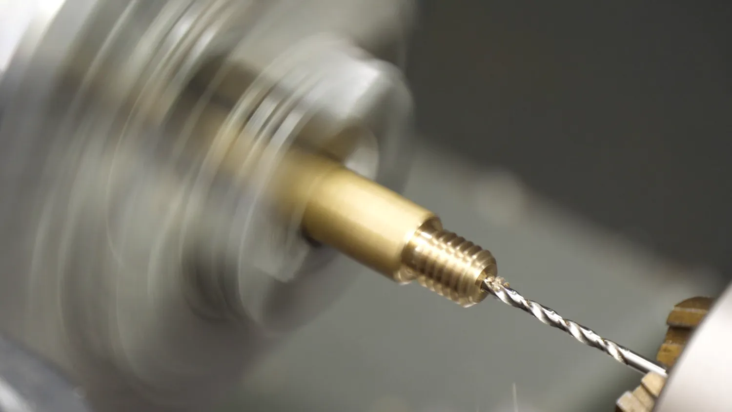
Drilling the 2mm hole
Second setup: the tip
Mounting the brass part on its threads in the three yaw chuck would ruin it, so I threaded a piece of aluminum rod, that’s then mounted in the chuck and in which I screw the nozzle blank. A collet chuck would have also been an option, but that would have required me to change it. I faced the part off and had to slightly readjust the tool height because it left a small bit of material where we soon want to drill with our tiny drill bit, for which we need a perfectly flat surface.
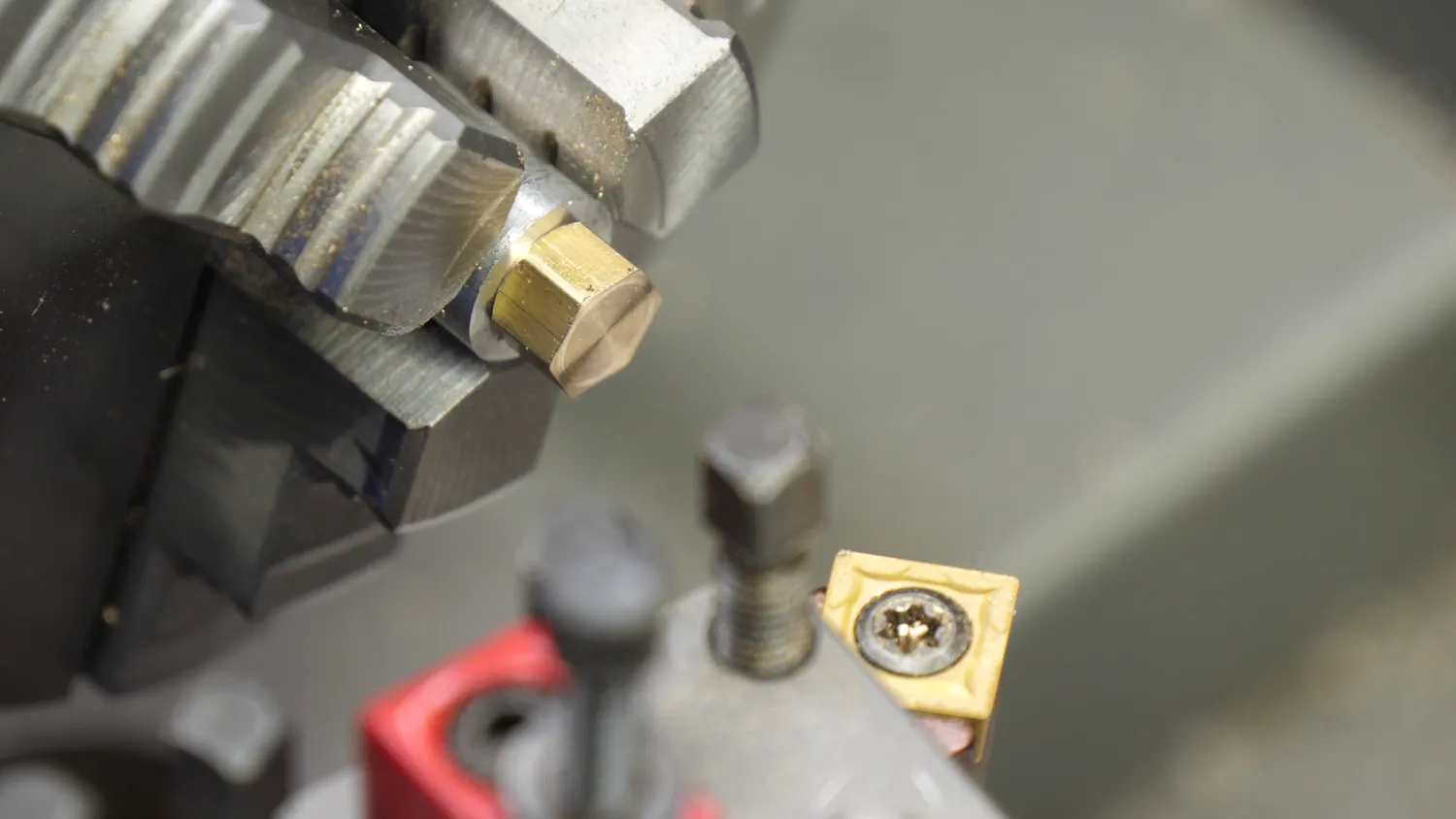
Nozzle Blank in Aluminum Holder
For machining the tip, I again used the square insert tool that we also used for the chamfers. The drawing asks for a 70° tip, but the standard orientation of the tool is 90°. I could rotate the whole compound, but that’s a pain on the Mini Lathe. Instead, I moved the toolholder just one set of teeth further on the MultiFix toolpost, which is 9° instead of the 10° required, but I guess good enough for our application. I zeroed the compound dial at the face and the cross slide roughly at the hex. I moved the tool 2mm in and then plunged into the hex to create the tip. This operation is something that this tiny lathe doesn’t really like, because at some point, a considerable portion of the tool is in touch with the workpiece creating huge cutting forces. Still, it made it with acceptable surface finish. Measuring the diameter of the tip is quite tricky, but I did my best to stay within the tolerances.
Drilling the 0.4 mm orifice
At last, we have to drill the orifice with the tiniest drill bit I’ve ever used. I made a pilot hole with the smallest center bit I could find but still had to pay attention that I only just slightly touch the tip because the center bit has a diameter of 0.5mm, which would result in a stepped tip and wouldn’t be optimal. For these drilling operations, I ran the machine at its maximum 2500 RPM to keep the cutting speeds high, but it would have been better to increase it even more. Next, I mounted the 0.4mm drill bit in the drill chuck, made sure that the ways are clean so that the tailstock is centered, and just went for it. We have some slight wobble in the beginning but quickly start drilling. And there we have it, the finished nozzle! Doesn’t look too bad, does it? Performing the operations in this order left no burr in the nozzle orifice and left us with a nice and sharp corner.
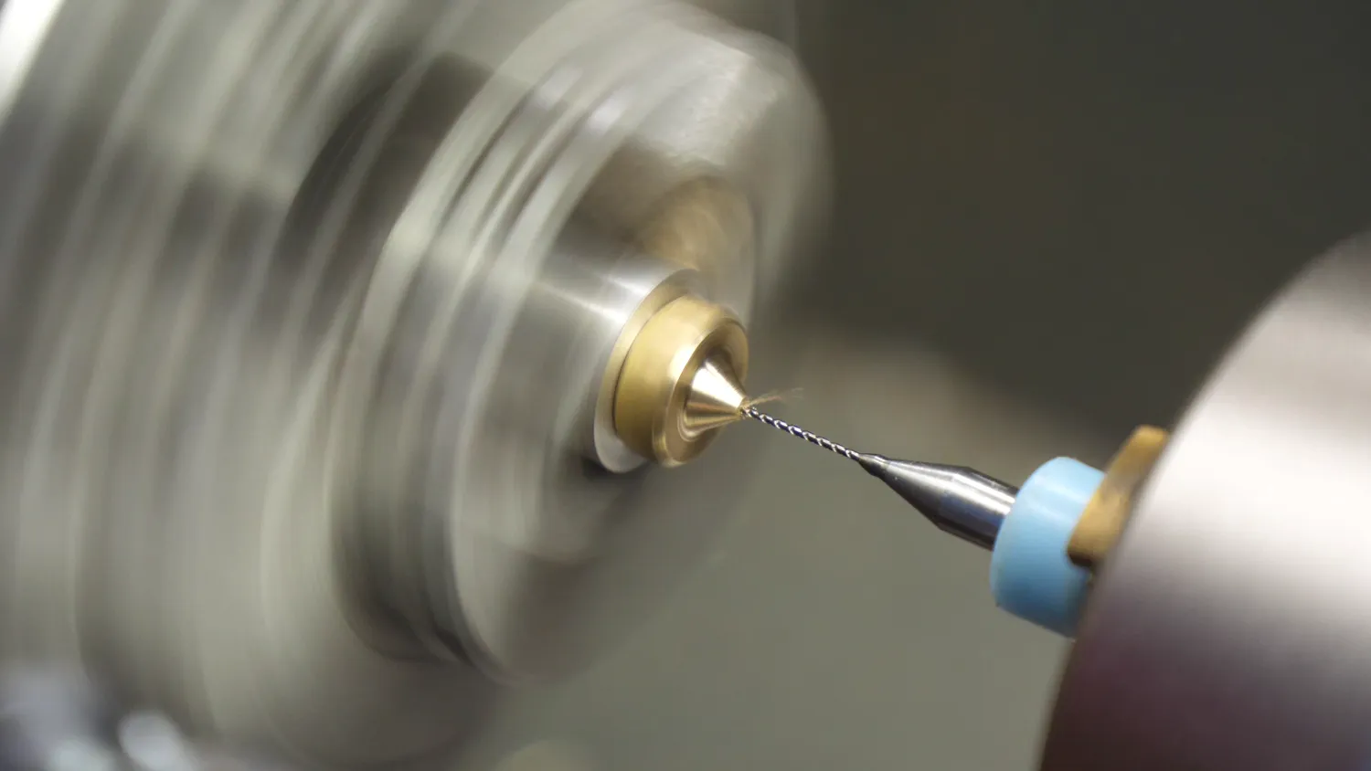
Drilling the 0.4mm Nozzle Orifice
Cutting it open
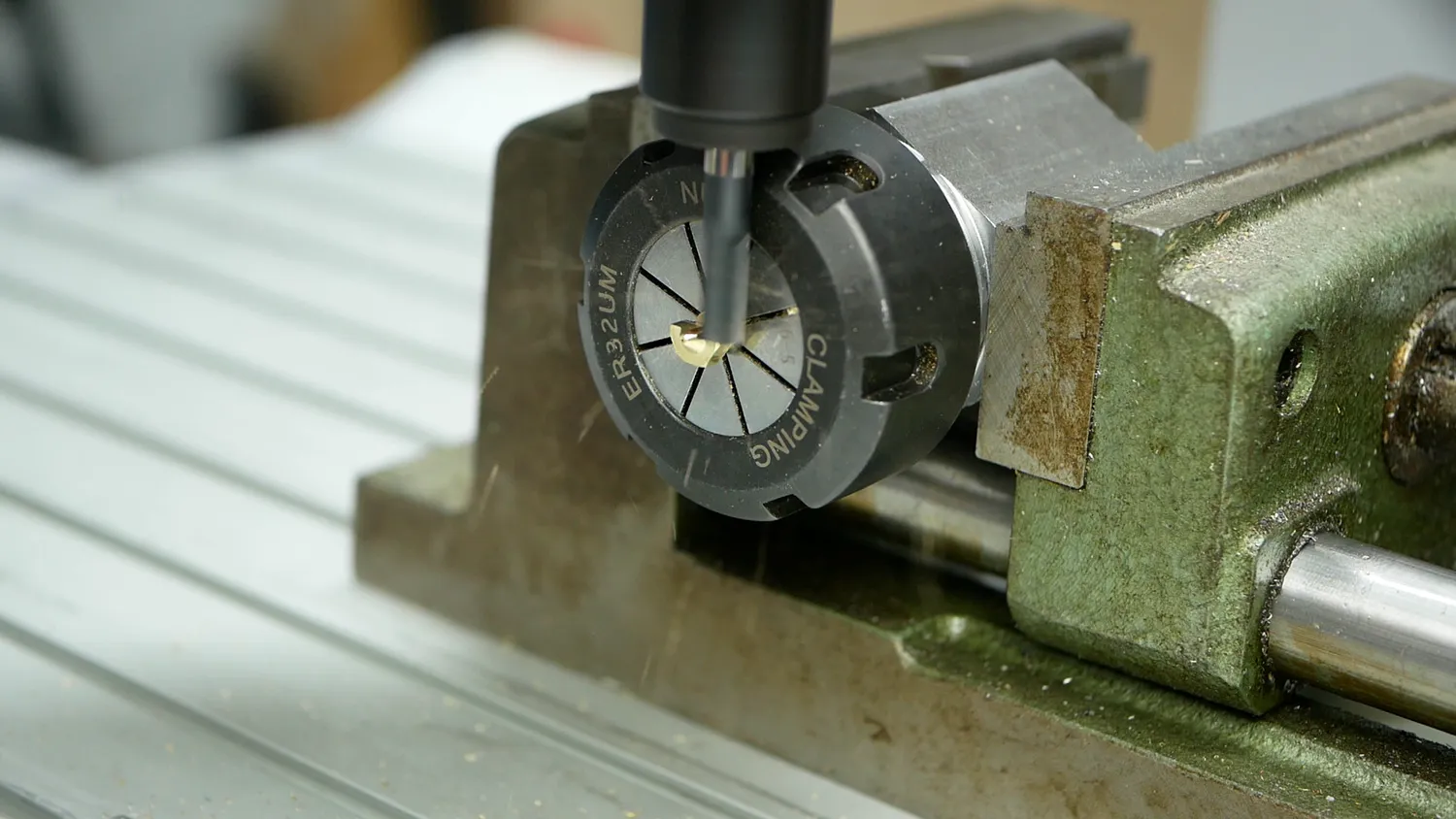
But the proof of the pudding is in the eating and I’ve therefore printed a test part with it and also cut one open to take a look on the internal surface finish. To dissect it, I put it into a collet block which I mounted in a vice on my CNC router and just machined half of the nozzle away in 0.5mm increments using a 6mm, three-flute carbide cutter.
So let’s take a closer look at it. Surface finish is not perfect, but I think very acceptable and way better as I’ve seen on other nozzles in the past. The depth of the internal bores were a bit too shallow, which leaves us with a nozzle bore that is a bit too long. Still, I think a very acceptable result for my skill level and the cheap machine I made it on.
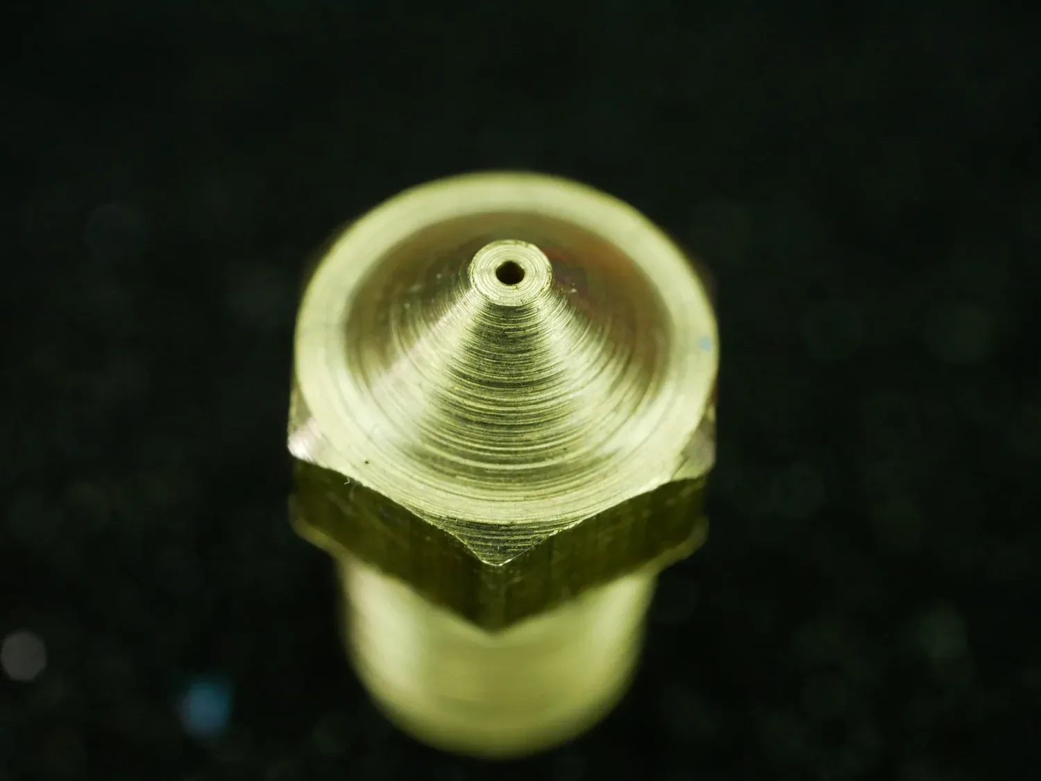
Nozzle Tip
How it prints
I machined several nozzles the last days, so let’s also test another one how it prints. I removed the genuine E3D nozzle on tool 2 of my E3D toolchanger and printed two 3DBenchys side-by-side. First, the one with a genuine E3D nozzle is finished, then the tools are changed and we print with my own, self-made nozzle. At first glance and even on closer inspection, there isn’t any significant difference besides the color visible, and I’d say, my nozzle didn’t perform any worse.
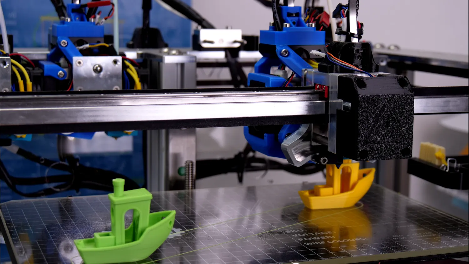
Printing 3DBenchys for Benchmarling on the E3D Toolchanger
If that’s due to my machining skill or because a 3D printer nozzle doesn’t need to be perfect is a question for another video. But what do you think about this project and what are your ideas and designs that you’d like to see tested in the future? Should I do more videos using the Mini Lathe? Let me know down in the comments!
Buy a Mini lathe and ACCESSORIES
Mini Lathe (aff): https://geni.us/OMvoY*
Carbide toolset (10mm / 3/8”) AMAZON (aff): https://geni.us/Qd0BD*
Carbide toolset (10mm / 3/8”) ALIEXPRESS (aff): https://geni.us/1qqmqZ*
Multifix Tool Post Size Aa AMAZON (EU) (aff): https://geni.us/A7HA1l*
Multifix Tool Post Size Aa ALIEXPRESS (aff): https://geni.us/BonNVcQ*
Thread pitch gauge AMAZON (aff): https://geni.us/aECDES*
Thread pitch gauge ALIEXPRESS (aff): https://geni.us/h0gNW*
Mitutoyo Calipers AMAZON (aff): https://geni.us/yzlblI4*
Mitutoyo Dial Gauge AMAZON (aff): https://geni.us/B4rCh*
ER32 Collet Chuck ALIEXPRESS (aff): https://geni.us/Wvdz*
ER32 Collet Block ALIEXPRESS (aff): https://geni.us/CodoS9m*
ER32 Collet Set ALIEXPRES (aff): https://geni.us/viUg1*
ER32 Collet Set AMAZON (aff): https://geni.us/GUgWC*
* Links marked with an asterisk are affiliate links — if you buy through them, I earn a small commission at no extra cost to you. As an Amazon Associate I earn from qualifying purchases. Thanks for supporting my work!