
Anti-Aliasing for FDM 3D Printing Is Finally Here (Micro-Non-Planar Printing)
Z Anti-Aliasing smooths FDM stair-stepping by varying layer height inside a layer. Ra drops from 80 to 25 µm on shallow slopes, measured, plus the limits.
TL;DRthe short version
- Z Anti-Aliasing (ZAA) varies the layer height within a layer on up-facing surfaces, so the top follows the real geometry instead of stepping. No hardware modification necessary.
- It's a checkbox in a fork of Bambu Studio by Aleksandr Dobkin, built on Theaninova's OrcaSlicer post-processor and on a 2017 paper by French researchers.
- On shallow slopes the roughness drops from around 80 microns Ra to just 25 microns, more than a threefold improvement, and the ZAA parts stay at a very consistent level across all angles.
- At 25 degrees the step length gets smaller than the extrusion width, so the path can't be moved anymore and both curves converge. Steeper than that, ZAA does nothing.
- For post-processing it's dramatic: after two rounds of filler and sanding, the conventional sphere half only reached the roughness the ZAA part had straight off the printer.
- 0.2 mm with ZAA is as smooth as 0.1 mm conventionally, and 0.3 mm with ZAA stays almost identical: three times the layer height at nearly constant top roughness, which is worth roughly 50% print time on some parts.
- The biggest open problem is that the nozzle is wider than the extrusion, so filling a surface from high to low still drags it over already printed lines. There are also gaps from z-heights that aren't reset and flow transitions that jump.
- My take: a great proof of concept, and unlike most non-planar approaches it isn't limited by hardware, so this could realistically be integrated into mainstream slicers.
Today we’re going to talk about anti-aliasing - and not the kind you know from video games, but anti-aliasing in 3D printing. This is a new method of non-planar printing that can be activated by a simple checkbox in a special version of Bambu Studio and that tremendously reduces the stair-stepping effect on FDM 3D prints. With just a bit of slicer trickery, you get sub-layer accuracy, especially on shallow-sloped surfaces. And this method doesn’t require any special hardware, is more or less universally usable, and with just a bit more work could make 3D prints smoother and more accurate. So let’s find out more!
Thanks to Mitutoyo for sponsoring this video and for providing their new Surftest SJ-220 Portable Surface Roughness Tester. This amazing piece of measurement equipment helped me put numbers to something I was previously only able to subjectively grasp by feeling and scratching the samples.
Why almost every 3D print is really 2.5D
Almost every 3D print that is made these days is, in reality, more of a 2.5D print. What I mean by this is that even though the process itself produces a three-dimensional object, the way parts are typically printed is by stacking two-dimensional layers on top of each other. Most of the time, the printhead only moves in a flat plane when it’s laying down material, and only after one of these layers is finished does the nozzle move up by one layer height and continue printing the next one - creating the typical stair-stepping effect we see on additive parts. But this is still how most thermoplastic, resin, and even metal 3D prints are produced.
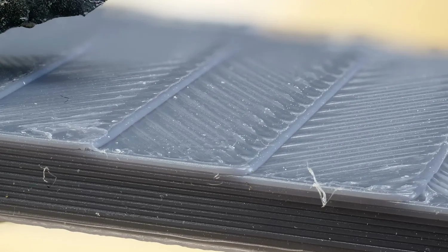
The typical stair-stepping of a conventionally sliced part
The reason for this approach is pretty simple. 3D printing preparation software is called a slicer because it cuts the three-dimensional models into thin slices and then processes these slices and fills them with print moves. This isn’t just mathematically simple and robust, it also avoids collisions with other parts of the print, because the printhead always moves above the highest point of the model.
Non-planar printing and why no slicer has it
So in order to get away from stair steps, we’ve seen several different approaches to non-planar printing over the last few years. Non-planar means that the layers are no longer flat planes, but instead curved to better follow the geometry. Sometimes this approach is only used for the top layer, but in other cases every layer is printed in a three-dimensional fashion. So you might ask yourself why non-planar printing is not a feature in any major slicer today.
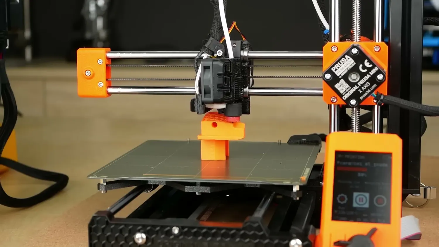
Conventional slicing keeps the nozzle in a flat plane
In my opinion, there are two major reasons for this. The first is that non-planar slicing is simply complex. There are so many edge cases where it just doesn’t work, so there is currently no general non-planar algorithm, and most examples focus on relatively simple geometry. The second reason is hardware. If you want to print non-planar, the printhead is constantly moving up and down. And since the cooling shroud of a printer is typically very close to the nozzle, the slicing algorithm has to ensure that no part collides with already printed sections. This has led in the past to some very interesting hotend and cooling shroud designs. So general non-planar slicing in this sense is simply not easy.
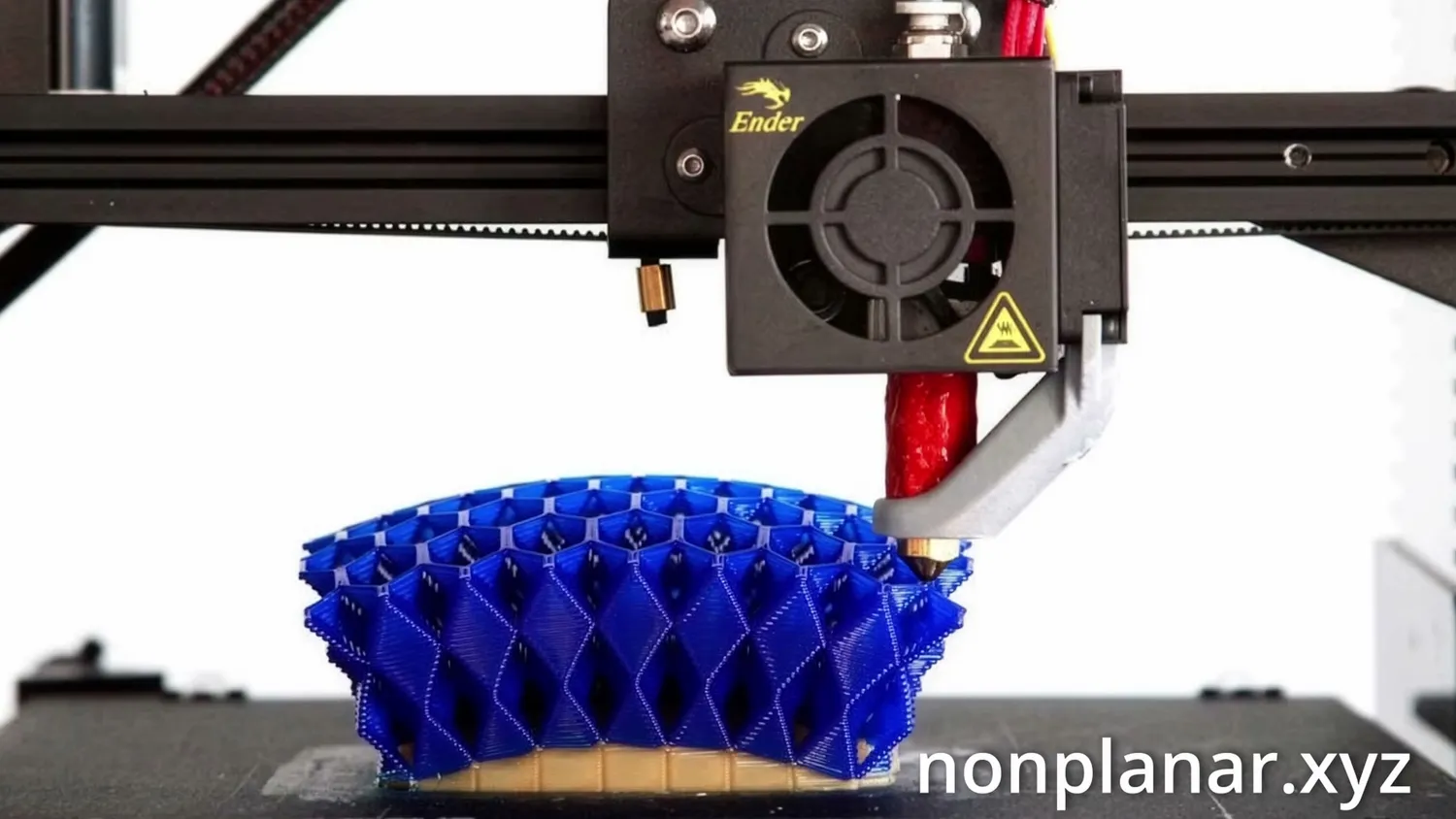
Full non-planar printing with a modified printhead (nonplanar.xyz)
What Z Anti-Aliasing does
But this is exactly where Z Anti-Aliasing, or ZAA for short, comes in. If you’ve ever played a video game or worked with computer graphics, you know that anti-aliasing is used to reduce the visible stair-stepping you get when diagonal or curved edges are approximated by square pixels.
Without anti-aliasing, an angled line on a screen can only jump from one pixel to the next, creating that jagged, blocky look. Anti-aliasing works by slightly adjusting or blending those pixels so the edge follows the intended shape more closely, even though the underlying grid is still there.
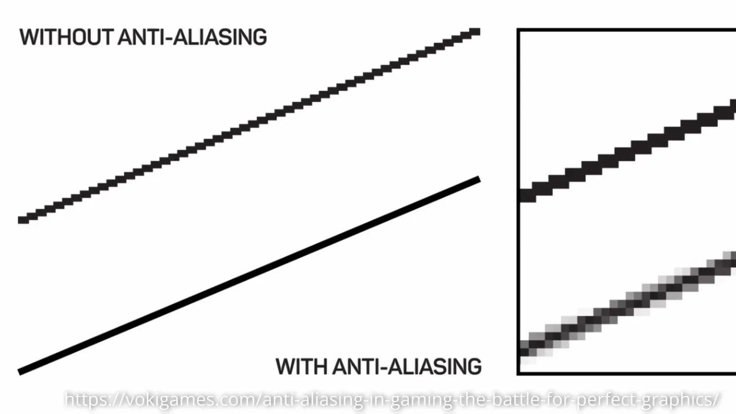
Anti-aliasing in computer graphics (vokigames.com)
Z Anti-Aliasing applies the same idea to 3D printing. Instead of square pixels, we’re dealing with flat layers stacked on top of each other. And instead of smoothing things in X and Y, ZAA smooths the surface in the Z direction by making tiny, controlled height adjustments within a layer. The part is still sliced into layers, but the top surface is no longer forced to be perfectly flat at each step; it can gently follow the actual geometry of the model.
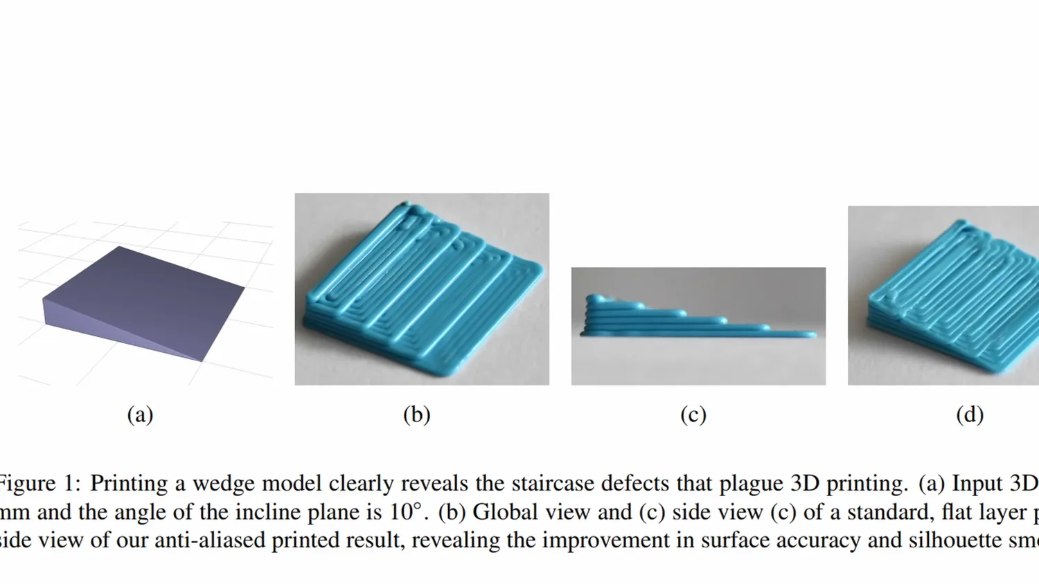
A wedge model reveals the staircase defect clearly (Song et al.)
The initial idea for this appeared in a 2017 paper by French researchers. Theaninova, without even knowing of the paper’s existence, implemented a similar idea two years ago as a post-processing script for OrcaSlicer, which Aleksandr Dobkin then used as the basis for creating a version of Bambu Studio that I’ve been using here. You simply download it, and you get a new option under the Quality tab in ZAA Bambu Studio. When you turn it on and slice a part, you can already see that layers on sloped surfaces that used to be completely flat are now slightly contoured, following the shape of the part much more closely.
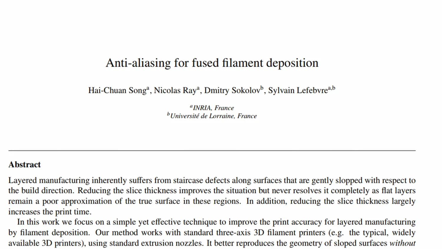
The 2017 paper by Song, Ray, Sokolov and Lefebvre
When you print a part, it doesn’t look dramatically different at first glance compared to one without ZAA. But when you touch or scratch it, you immediately notice that the discrete steps on top surfaces are almost gone, and the print feels noticeably smoother. You can still feel that the surface has a roughness similar to that of any other top surface of a print, but the steps are almost gone.
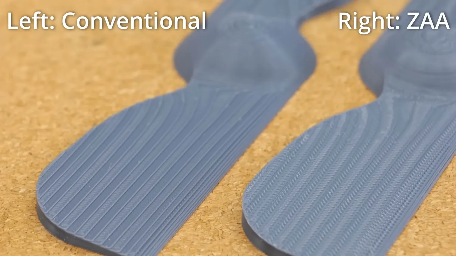
(left) conventional, (right) Z Anti-Aliasing
How the algorithm follows the slope
The way Z Anti-Aliasing works is both simple and very clever. First of all, it only affects top surfaces of a part, so most areas of a print aren’t touched at all. To illustrate the method, let’s look at the side of a simplified part. The dashed line represents the edge of our geometry. In conventional slicing, the part is cut in the middle of a layer, and the nozzle moves on a plane while extruding plastic. Then the nozzle moves up by one layer height and does the same thing again, creating the typical FDM stair steps.
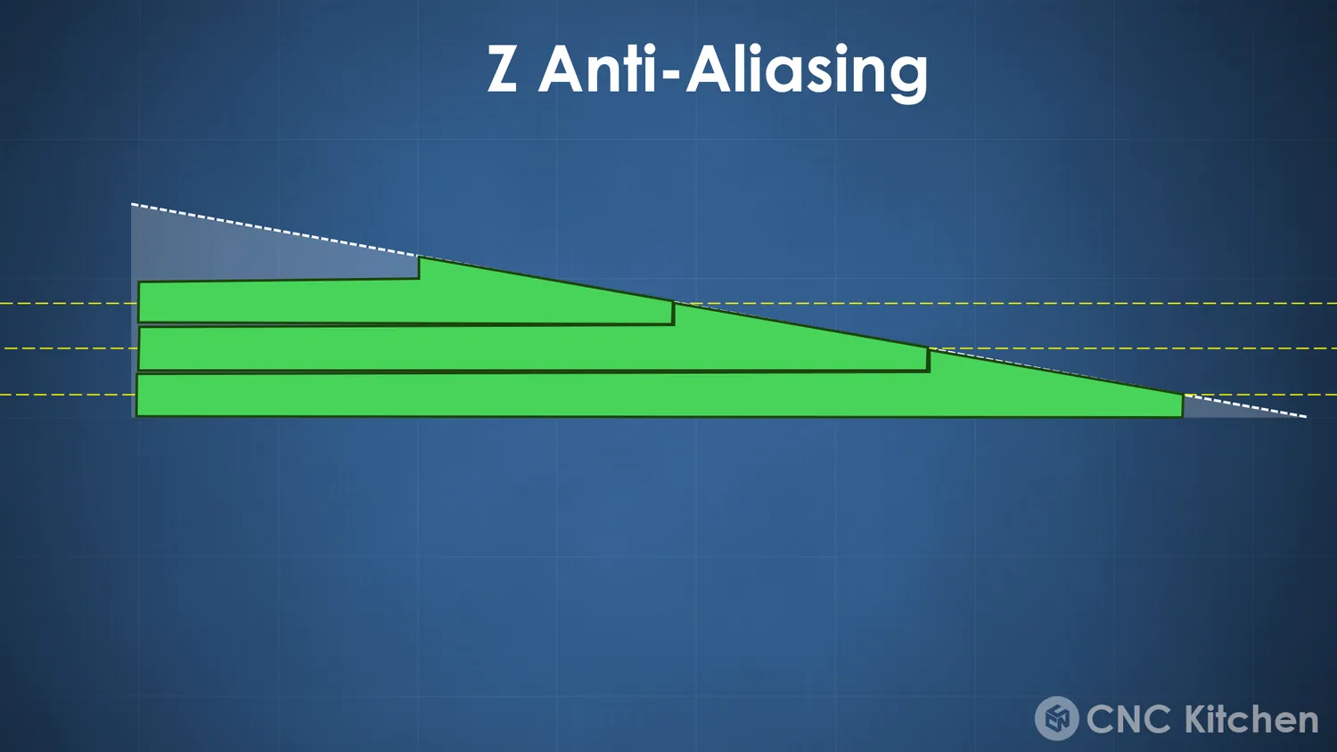
The layers follow the dashed geometry instead of stepping across it
Z Anti-Aliasing is smarter than that. The algorithm projects the toolpath of up-facing, outer surfaces onto the actual geometry and therefore follows the shape of the part by dynamically varying the layer height in a small margin. This way, you avoid most of the major collision problems associated with other non-planar approaches, while still following the slope of a part almost perfectly. And this doesn’t just get rid of stair-stepping - dimensional accuracy also improves, because you get rid of over-extrusion in some areas and fill voids in others.
Measuring the surface roughness
And you can’t just feel that effect - you can measure it.
Let’s start by measuring the effect of Z Anti-Aliasing on these simple samples with surface angles of 5, 10, 15, 20, and 25 degrees. Both sets were printed at a 0.2 mm layer height in PLA, with the only difference being that ZAA was enabled for one and disabled for the other. Even though you can’t easily see the difference from above, a closer inspection reveals visible stair-stepping on the conventional part, while it’s almost gone on the ZAA sample. I measured each slope twice by gently placing the measuring tip of Mitutoyo’s Surface Tester onto the part. Within a few seconds, the tester drags the tip over the surface, measuring the surface profile, and then processes it to give me the roughness values. I focused on Ra, which is the arithmetical mean roughness. In simple terms, it’s the average height deviation of the surface from a perfectly smooth reference line. If you imagine dragging your finger across a surface, Ra is a good indicator of how smooth it feels overall. Lower Ra means a smoother surface.
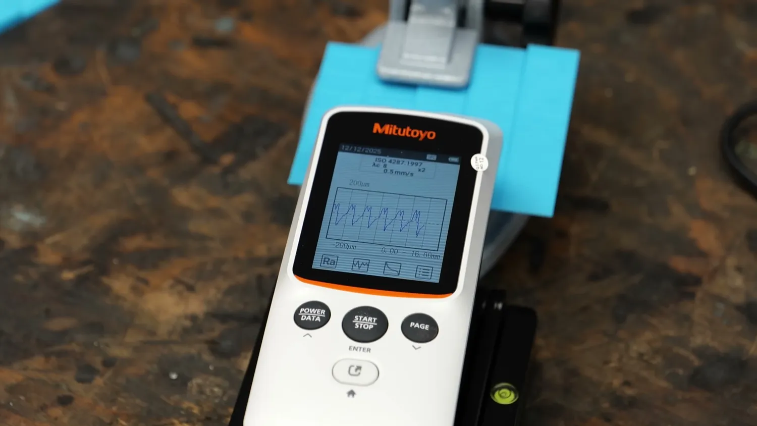
The measured surface profile of a sloped sample
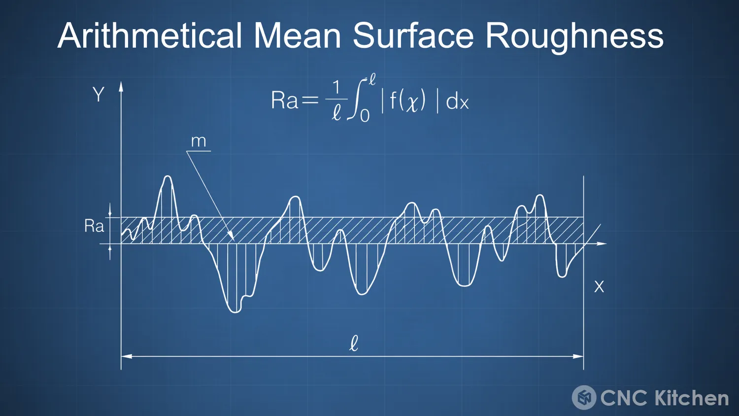
Ra is the average height deviation from a smooth reference line
The biggest improvement is visible on shallow slopes, where stair-stepping is normally most pronounced. Here, the conventional Ra roughness is around 80 microns, compared to just 25 microns with Z Anti-Aliasing. That’s more than a threefold improvement. As the slope angle increases, the conventional roughness gradually decreases, but the ZAA parts are always smoother and, interestingly, at a very consistent level.
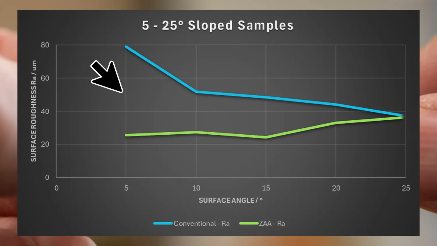
Surface roughness of the 5–25° sloped samples
At some point - here at 25 degrees - the curves converge. At this point the step length is smaller than the extrusion width, so the path can’t be moved anymore. At even steeper angles than this, ZAA simply doesn’t have an effect anymore, and you’re left with the roughness inherent to the technology.
These numbers also show that Z-contouring clearly works. Visually, it may not look as dramatic as some other non-planar approaches we’ve seen in the past, because the top surface is still divided into individual layers and you can see the boundaries. But there are still some very significant advantages.
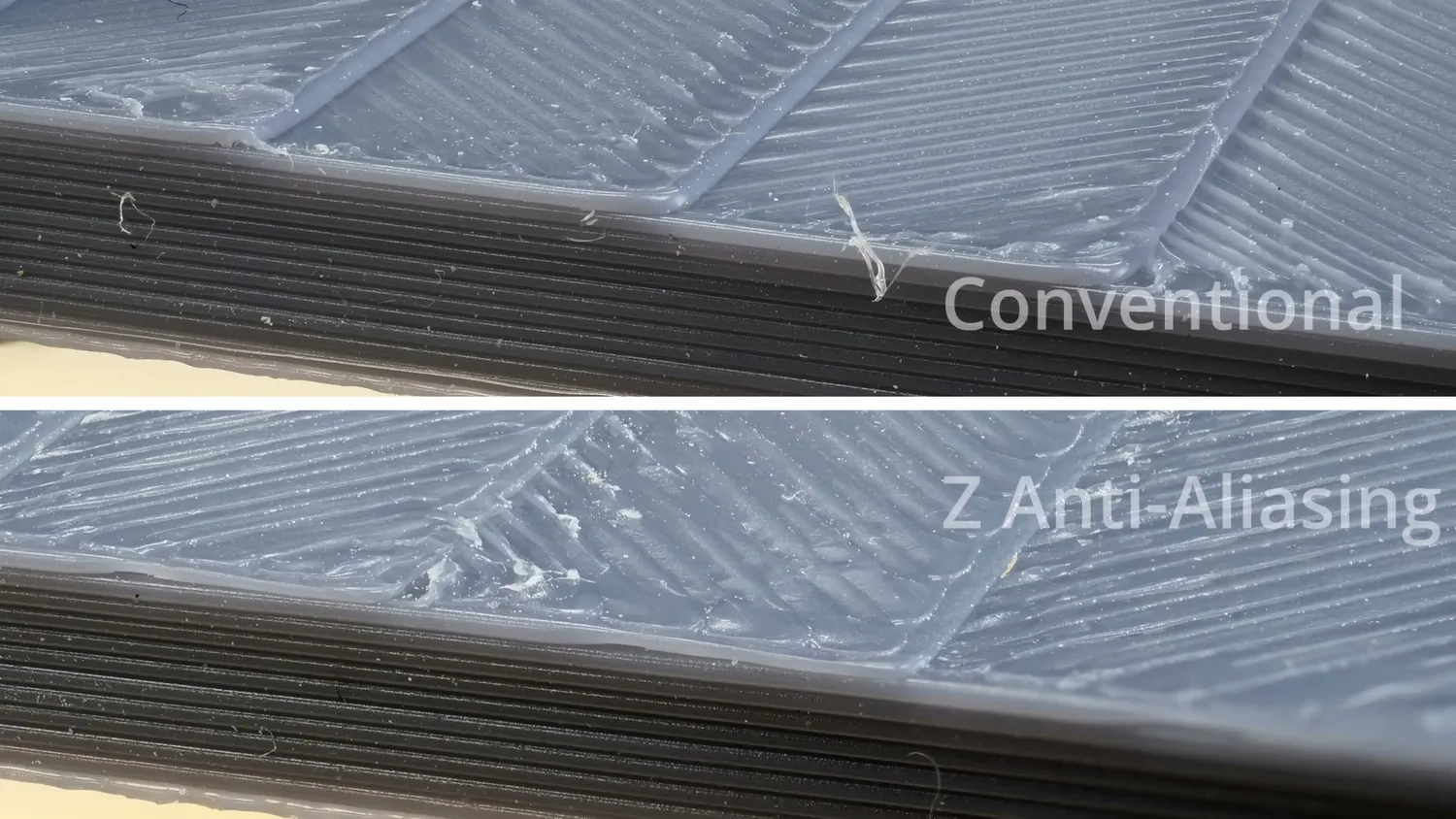
(top) conventional, (bottom) Z Anti-Aliasing
Sanding and filling gets much easier
One of them is post-processing. When sanding and filling parts in the past - especially on shallow slopes - you often had to fill deep voids and sand down excess material over and over. To illustrate this, I printed the top halves of a sphere. This could be something like the top of a helmet - one with ZAA and one without. I measured surface roughness in three directions. The conventional part started with an Ra of 50 microns, while the ZAA part was already down to 21 microns.
I then applied spray filler, which really highlighted the stair pattern. After letting it dry overnight, I lightly sanded both parts and measured them again. This first post-processing step roughly halved the roughness of both samples, but neither was perfect yet. After a second round of filler and sanding, the ZAA part again nearly halved its roughness and already felt extremely smooth, while the conventional part only showed a small improvement. In the end, the conventionally printed part only reached the same roughness level as the ZAA part had straight off the printer - and I think that clearly shows how powerful this technique can be, especially for anyone who post-processes their parts or needs smooth sliding surfaces in mechanical applications.
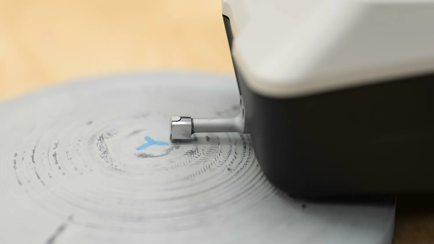
Measuring the sphere halves after filler and sanding
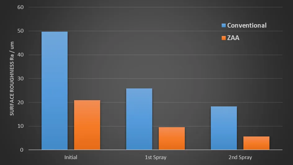
Surface roughness of the sphere halves after each round of filler and sanding
Thicker layers at the same smoothness
The other big point is print time. I printed several test parts at different layer heights, because with conventional slicing, the thicker the layers become, the rougher they are, simply because the steps between the layers become steeper. But with Z Anti-Aliasing, we can smooth that out!
When we add the ZAA results to the plot, something interesting shows. A part printed at 0.2 mm layer height with ZAA is just as smooth as one printed conventionally at 0.1 mm. And it gets even crazier: if we increase the layer height to 0.3 mm and keep ZAA enabled, the surface roughness stays almost exactly the same. This means we can theoretically print at three times the layer height while keeping top surface roughness nearly constant.
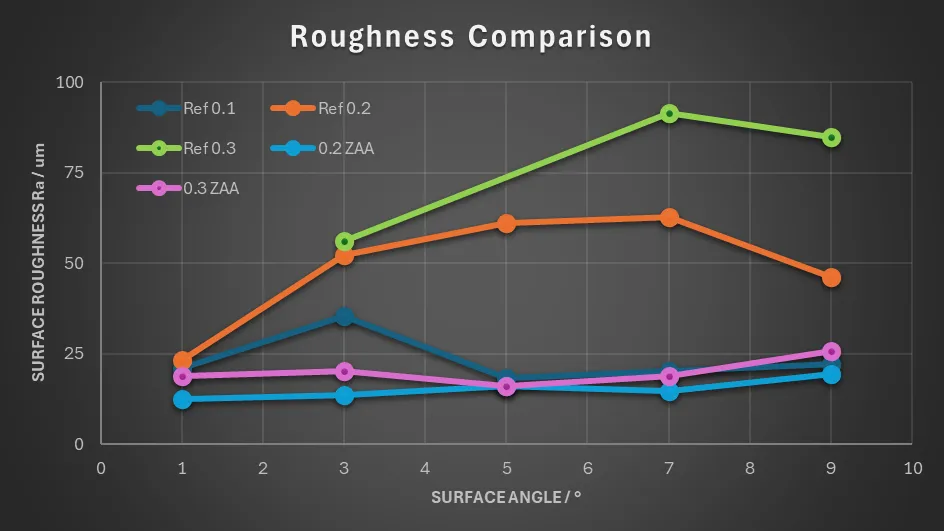
0.2 and 0.3 mm with ZAA both stay at the level of conventional 0.1 mm
A few years ago, when printers were primarily speed-limited by their movement speed, this meant massive print-time savings. Today, with fast machines that are often melt-rate limited, the benefit is smaller - but a print-time reduction of around 50% is still very realistic for some parts because Z Anti-Aliasing shouldn’t add a significant amount of print time due to only small print movements.
You might ask whether variable layer height, a slicer feature we already had for years, could also be a good solution for smoother top surfaces. And in a way, it does - but it has two downsides. First, it adds more layers, which increases print time. Second, while it works well for simple parts, complex geometries almost always have at least one shallow section at every layer, which forces the entire part to be printed at lower layer heights. Z Anti-Aliasing, on the other hand, lets you print the whole part with thicker layers and only modifies the toolpaths exactly where it’s necessary.
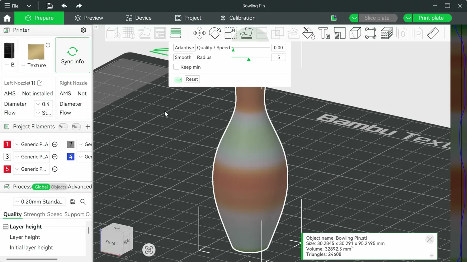
Variable layer height works well on simple, rotationally symmetric parts
Where Z Anti-Aliasing still struggles
Up to this point, this all sounds pretty amazing, so you might be wondering why this isn’t already part of mainline Bambu Studio or OrcaSlicer. As always, there are some challenges - but in my opinion, they’re much smaller than with other non-planar approaches.
My explanation so far has been simplified, and reality is a bit more complex. You might have already noticed on some printed parts that surface quality with ZAA can vary over a print. Earlier, I said that ZAA avoids the collision problems of other non-planar approaches - and while that’s mostly true, it’s not entirely. Even though the cooling shroud isn’t an issue, the nozzle itself can still collide with already printed material, because the lower part of the nozzle is typically wider than the extrusion.
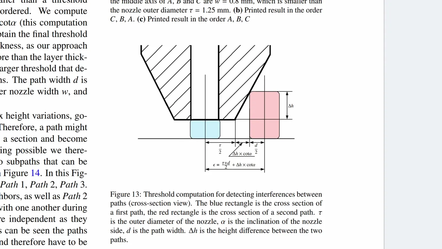
The nozzle is wider than the extrusion it lays down (Song et al.)
The current ZAA implementation takes planar toolpaths and adjusts only the Z component to better follow the geometry. This can lead to problems depending on the order in which the lines are printed. If a surface is filled from low to high, everything works fine. But if it’s filled from high to low, the side of the nozzle can collide with previously printed lines, leading to rougher surfaces. On complex prints, this is almost unavoidable and shows on the parts right now.
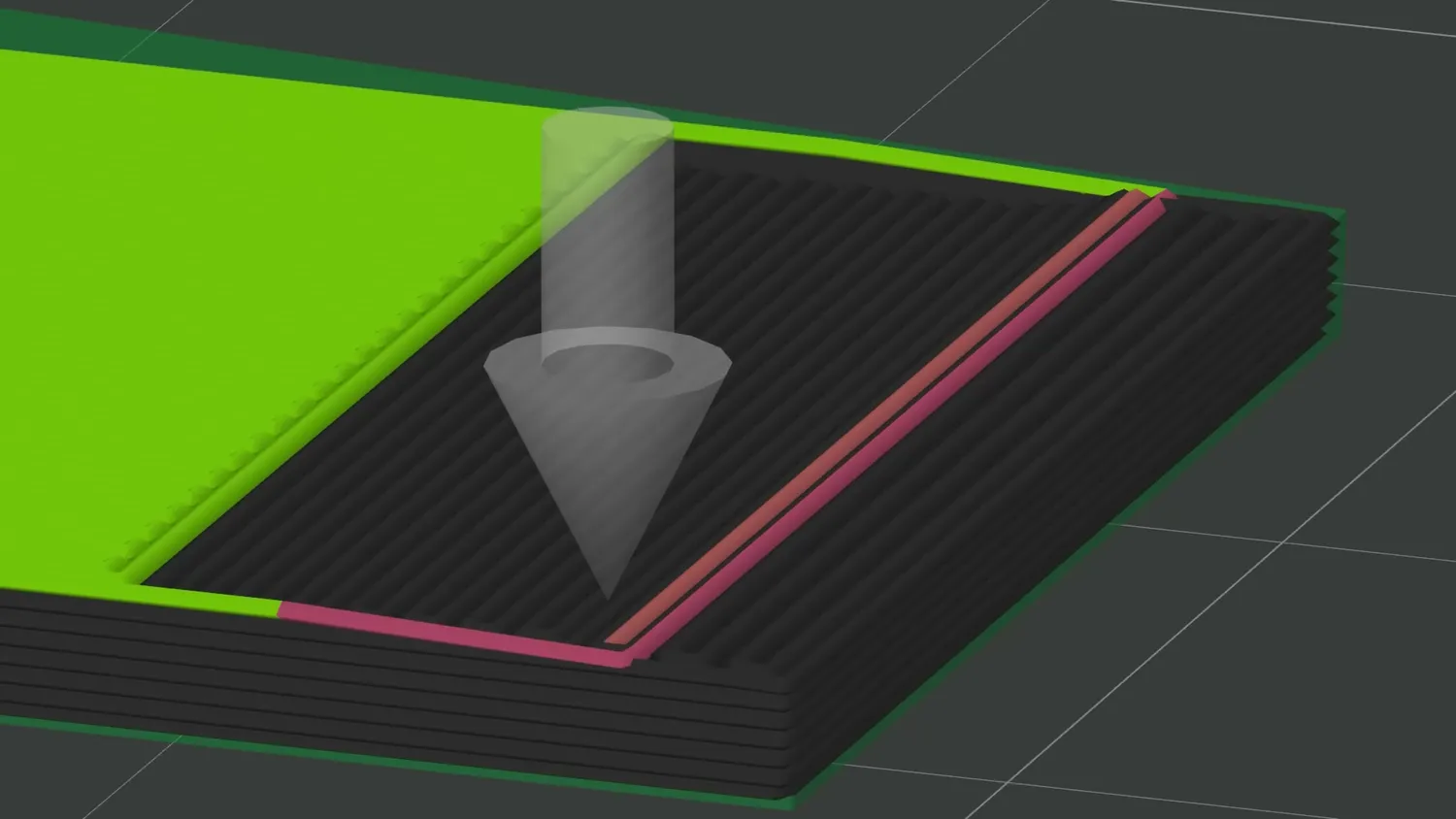
Filling from high to low drags the nozzle over finished lines
Solving this properly will likely be the biggest task before ZAA becomes a fully finished feature. We should already be able to get better results if we used pointy nozzles where the lower part doesn’t have that big flat section anymore, but this would kind of defeat the “no-hardware modification necessary” premise. There is also another solution. The original 2017 paper splits extrusion paths by height and prints them from lowest to highest, avoiding interference entirely. Since this creates a large number of individual paths, the authors also propose an optimization algorithm to reduce travel moves and also place the remaining seams in less visible areas. Going into more detail would be too much here, so if you’re interested, have a look at the paper.
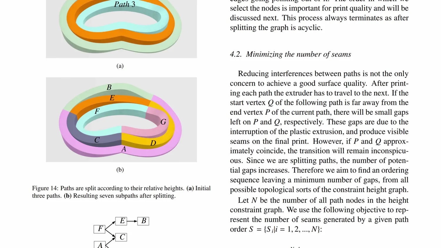
The paper splits paths by height and prints them lowest first (Song et al.)
There are also still some minor bugs and edge cases in the current implementation. Sometimes I had gaps between the layers because the z-height wasn’t reset. I also noticed gaps in my top layers. Upon further inspection, I saw that on flat, sloped surfaces, the extrusion transitioned from low to high or high to low, but it jumped depending on the direction. You see, our 3D printer G-Code doesn’t have a command to move from point A to point B and transition from low to high material flow, as would be necessary for our variable layer height. So we typically divide paths and vary flow in steps. Sometimes the current implementation does that, like on the sphere, but it doesn’t do that on my wedges. But this can all be polished, and overall, I think this is a technique that could realistically be integrated into mainstream slicers - unlike many other non-planar approaches that are limited by hardware constraints.
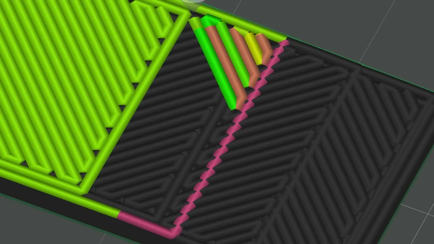
The transition from low to high flow along the slope
My take on Z Anti-Aliasing
In my opinion, Z Anti-Aliasing is a very exciting technique that again shows how much potential still lies in clever slicing algorithms. The current Bambu Studio implementation is already a great proof of concept, and with a bit more development, this could become an amazing option for smoother or faster prints - without all the complexity of full non-planar printing.
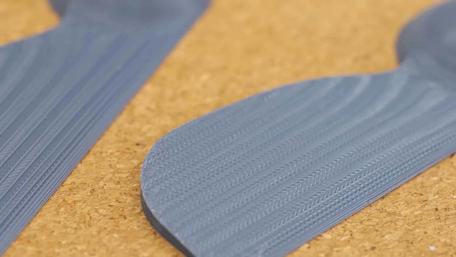
Smooth sloped surfaces straight off the printer
A big shout-out goes to Thea and Aleksandr for the massive amount of work they put into making this already usable today. But what do you think about Z Anti-Aliasing? Would you like to see this as a standard slicer feature, or would you rather have true non-planar printing instead?